Abstract
The seismic performance of storage tanks is a matter of special importance, extending beyond the economic value of the tanks and contents. This has led to attention of many researchers due to the seismic behavior of tanks buried in the soil. Because of the interaction between soil and structure during an earthquake, dynamic analysis of such structures is very important that must be considered. In this paper, according to the interaction effect of soils and structures, under the time history record, seismic behavior of concrete cubic buried tanks has been analyzed using the finite element software ABAQUS. In this process circular and cubic tanks have been studied and the impact of changes in parameters such as earthquake and quantity of water in tanks on pressure on tank's wall has been studied.
1. Introduction
Earthquake brings huge losses in the development of human society repeatedly, which is one of the most serious natural disasters facing the humanity. The world's earthquake occurs about 500 million times every year, of which magnitudes 6 and above is about 100 to 200 times and magnitudes 7 and above is about 18 times. Earthquake loads have usually been considered in their design, but the analyses have been based on simplified theory developed for retaining walls with the wall top at the ground surface and the foundation assumed to be rigid. When the structure is constructed below the surface in deep soil layers, these simplified methods have obvious limitations.
So the earthquake force is an important factor for the design of such structures. This problem has caused in the past years, many researchers have been considered the analyzing such structures under seismic forces. Jacobson [1] is among the first researchers that has carried out many studies on the dynamic behavior of water tanks in 1949. A decade later, Housner [2] studied on a simple dynamical model for the buried rectangular and cylindrical tanks. In the same years, Lysmer [3] proposed a theory of viscous absorbing boundary around a limited environment for modeling semi-constrained environment for analyzing buried tanks. But the main problem of absorbing boundaries is limitations to analyzing in the frequency domain. This led to Lysmer continued his research of absorbing boundaries and in 1969 Lysmer and Kuhlemeyer [3] and in 1972 Lysmer and Wass [4] provided other additional models based on the theory of absorbing boundaries.
Research in this area did not stop his studies and other researchers like Kausel [5] presented research in this field. In 1992, Haroun [6] used and expanded studies of Housner [2] for flexible reservoirs. He offered empirical model for the reservoir according to soil structure interaction effects and explained soil structure interaction effects with several experiments on turbulence in the water. He collected valuable information on soil structure interaction effects from previous researchers and their experiments. Thus evaluation of soil structure interaction is considered an important factor for the analysis of buried tanks. Appropriate methods of dynamic analysis of structures with regard to interaction effects and soil structure are formed based on finite element method [7]. Finite Element Method (FEM) is the most widely used numerical methods in structural analysis that includes nonlinear effects, what type of material and geometry [8]. Most research on soil and structure interaction studies based on finite element method is analyzing two-dimensional tanks models based on different software. However, in some cases three-dimensional model of the comment is taken into account [9-10].
In another research work, Lin et al. [11] rebuilded the computer model of condensate storage tanks in Taiwan using the SAP 2000 program in conjunction with the lumped mass stick model and to evaluate the soil structure interaction by employing the SASSI 2000 program. The differences between the results with the soil structure interaction and spring model were compared via natural frequency and response spectrum curves.
2. Seismic analysis of buried tanks
Seismic behavior of buried tanks is dependent on the surrounding environment. In general, because dynamic model of a complete system include the dynamic model in relation to surrounding structures, wave propagation conditions in tank environment and the interface between tanks and their surrounding environment must be considered. In other words, buried tanks and surrounding soil during an earthquake is in the interaction. This problem is very important for bulky and heavy structures such as tanks. One of the factors in the seismic analysis of buried tanks is soil structure interaction.
3. Simplified fluid–structure interaction
The seismic analysis of liquid storage tanks is complicated due to fluid–structure interaction of the system. Therefore, complex actions must be taken into account. First of all, the contained liquid is interacting with the tank wall. Seismic energy is transferred from the ground to the fluid through the motion of the tank. A portion of the liquid accelerates with the tank, acting as an added mass; the remaining liquid is assumed to slosh. Sloshing occurs in the upper part of the liquid, which does not displace laterally with the tank wall, generating seismic waves. In an effort to simplify the analysis, Haroun and Housner [12] developed a three-degree-of-freedom model of a ground-supported cylindrical tank that takes tank wall flexibility into account. Following is a review of this model. The contained liquid is considered as incompressible, inviscous and has irrotational flow. During the base excitation, the entire tank liquid mass (m) vibrates in three distinct patterns, in three distinct patterns, such as sloshing or convective mass (mc) (i.e. top liquid mass which changes the free liquid surface), impulsive mass (mi) (i.e. intermediate liquid mass vibrating along with tank wall) and rigid mass (mr) (i.e. the lower liquid mass which rigidly moves with the tank wall). While there are several modes in which sloshing and impulsive masses vibrates, the response can be predicted by considering only the first sloshing mode and the first impulsive mode. Therefore, the continuous liquid with flexible tank can be modeled as three lumped masses (see Fig. 1) [12].
Fig. 1Mechanical analog proposed by Haroun and Housner for flexible cylindrical tank [12]
![Mechanical analog proposed by Haroun and Housner for flexible cylindrical tank [12]](https://static-01.extrica.com/articles/14737/14737-img1.jpg)
The convective and impulsive masses are connected to the tank by corresponding equivalent springs. The various equivalent masses and associated natural frequencies of the tank liquid are expressed as [13]:
where H is the liquid height, R is the tank radius, S=H/R is the aspect ratio (ratio of the liquid height to radius of the tank), the non-dimensional parameters Yc, Yi and Yr are mass ratios associated with convective, impulsive and rigid masses of the tank liquid, respectively; qw is the mass density of liquid; xc and xi are the convective and impulsive frequencies, respectively; E and qs are the modulus of elasticity and density of tank wall, respectively; g is the gravity acceleration and P is a non-dimensional parameter associated with frequency of impulsive mass. The parameters Yc, Yi, Yr and P are function of the aspect ratio of the tank S, given by the following relation [13]:
The effective heights Hc, Hi and Hr in terms of liquid height, H are expressed as:
The equivalent stiffness and damping of the convective and impulsive masses are expressed as:
where ξc and ξc are the damping ratios of convective and impulsive masses, respectively [15].
4. Earthquake force and its components
In general each structure which is burial in soil affected by six components of ground motion during the earthquake. These components include two lateral components, one vertical component and three torsion components. Horizontal components of ground motion make hydrodynamic pressures exertion to the parapet of tank. Hydrodynamic pressures include pendulous and traumatic pressures. Hydrodynamic pressures may cause shear forces and bending moment and convoluted axial stresses and shear stress on the parapet of tank. Seismic behavior of structure is a complicated behavior that this problem cause more accurate in modeling of buried tank seismic behavior. Thus buried tank seismic behavior analysis needs seismic risk assessment until can estimate correct evaluation of structure performance during the earthquake. Seismic risk assessment can calculate ground motion parameters and records and spectral requirements.
5. Modeling of soil structure interaction effect based on finite element method
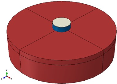
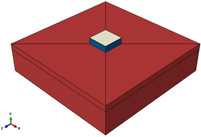
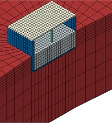
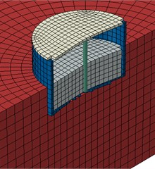
The important part of modeling in buried tank analysis is interaction between soil and structure. In general tow methods exist in Abaqus for contact solution. Penalty function method and kinematic contact method are two methods that are mentioned. In penalty functional method, there is no limitation for penetration two surfaces together. But in kinematic contact method, the value of penetration two surfaces together is zero. In this research kinematic contact method is used for modeling the slide between parapet of tank and soil with tangential parameter. According to this element in Abaqus can model friction between tank and soil and also nonentity endurance assumption of soil. This element has ability of considering soil and structure interaction. Homogeneous solid element is used for modeling the tank. Also homogeneous solid element is used for modeling the soil and water with regarding soil parameters. Solid element is six faced and eight node elements that in each node three degree of freedom exist. This model includes nonlinear behavior and can consider criteria yield for the soil based on the stress – strain yield surface. In modeling has been used Drucker-Prager behavior for soil behavior. 3D finite element models in Abaqus were presented in following figures.
The aim of this study is finite element modeling with estimation of damage to the concrete tanks. In this research, ABAQUS software is used for finite element modeling of the tank. The next step is to make the structure geometry, the tank and the foundation by elements relating to the available specifications. The boundary conditions are introduced to consider the interaction of the soil and the tank and also the applied loadings. In order to define the crack criterion in the concrete tank, the parameter of concrete damage plasticity (CPD) is used [14]. In this parameter, a strain criterion is determined for tensile and compressive stresses and the damage parameter is obtained for each strain. To model concrete, soil and water in ABAQUS, it is required to define parameters of Table 1-3. These parameters are considered in accordance with the software defaults.
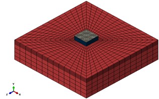
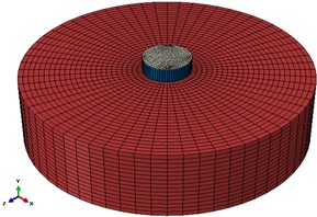
Fig. 3 demonstrates model meshing.
Fig. 2a) Circular tank 3D model and b) Cubic tank 3D model
(a)
(b)
Fig. 3Meshed model of tank in ABAQUS software
a)
b)
c)
d)
Table 1Used parameters in concrete definition [16]
Dilation angle | Eccentricity | σb0/σc0 | K | Viscose parameter | Poisson coefficient | Modulus of elasticity | Concrete density | ||
36° | 0.1 | 0.16 | 0.66 | 0 | 0.2 | 26.5 GPa | 7850 Kg/m3 | ||
Compression behavior | |||||||||
Yield stress (MPa) | Inelastic strain | Damage parameter | |||||||
15 | 0 | 0 | |||||||
20.2 | 7.47E-05 | 0 | |||||||
30 | 9.88E-05 | 0 | |||||||
40.3 | 0.000154123 | 0 | |||||||
50 | 0.000761538 | 0 | |||||||
40.2 | 0.002557559 | 0.195402 | |||||||
20.2 | 0.005675431 | 0.596382 | |||||||
5.3 | 0.011733119 | 0.894865 | |||||||
Tensile behavior | |||||||||
Yield stress (MPa) | Inelastic strain | Damage parameter | |||||||
2 | 0 | 0 | |||||||
2.8 | 3.33E-05 | 0 | |||||||
1.9 | 0.000160427 | 0.406411 | |||||||
0.86 | 0.000279763 | 0.69638 | |||||||
0.23 | 0.000684593 | 0.920389 | |||||||
0.056 | 0.00108673 | 0.980093 | |||||||
Table 2Mechanical properties of soil
Poisson’s ratio | Elasticity (kPa) | Cohesion (kN/m2) | Friction angle | Density (kN/m3) |
0.3 | 73000 | 0 | 38 | 1900 |
Table 3Mechanical properties of water
Water properties | ||||
Viscosity (Pa.s) | EOS (Us-Up) | Density (kg/m3) | ||
c0 | s | Gamma0 | ||
0.001 | 1450 | 0 | 0 | 996 |
6. Loading
In this study, the weight load and the force due to the fluid, soil and the tank body interaction are considered only. Records from earthquakes of Tabas (1978), Northridge (1994) and Helena (1935) are used for seismic stimulation of this case study tank. Fig. 4 to Fig. 6 show the parameters of these earthquakes in X direction.
Fig. 4Horizontal accelerogram parameters of Helena earthquake in X direction
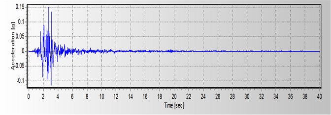
Fig. 5Horizontal accelerogram parameters of Northridge earthquake in X direction
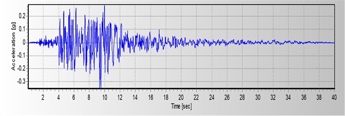
Fig. 6Horizontal accelerogram parameters of Tabas earthquake in X direction
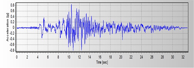
Table 4Accelerogram characteristics used in the analysis
Maximum acceleration (g) | Earthquake intensity (richter) | Occurrence place | Occurrence date | Earthquake name |
0.231 | 6.7 | California, USA | 1994 | Northridge |
0.173 | 6.0 | Montana, USA | 1935 | Helena |
0.852 | 7.35 | Tabas, IRAN | 1978 | Tabas |
In the analyses, the model is exposed to horizontal accelerogram. In order to apply loadings to the tank floor which is connected to the ground, the earthquake acceleration is applied like a real earthquake.
7. Helena earthquake loading
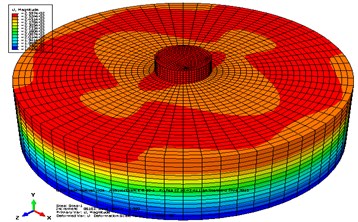
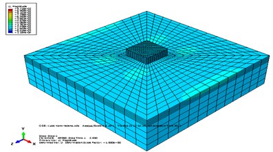
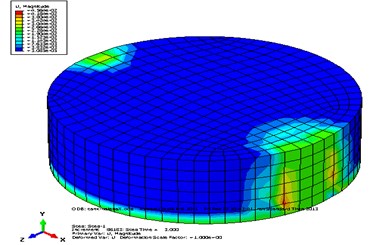
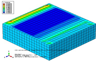
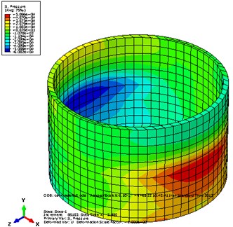
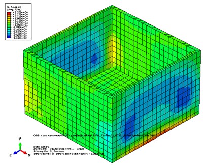
Helena earthquake is applied to the tank in X direction and the results have been reported and some comparisons have been done among them. The measure of stress in the tank buttress and in the connection place of tank to soil and the wall section of tank which is in contact with water is maximum and the disturbance made in the wall causes increase in internal forces of the structure; these forces are applied to the soil cumulatively. It is clear that the stresses made in the tank are due to these forces. These stresses are created in the soil and water and are transferred to the whole tank. Fig. 7-8 show model displacement and pressure stress contour due to Helena earthquake in horizontal direction.
Fig. 7Displacement contour of a) circular tank, b) cubic tank, c) water in circular tank, d) water in cubic tank
a)
b)
c)
d)
Fig. 8Pressure stress contour of circular tank and cubic tank
a)
b)
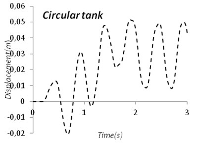
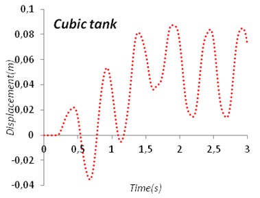
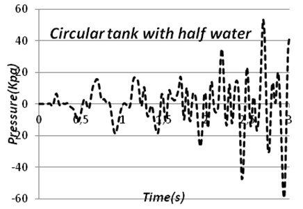
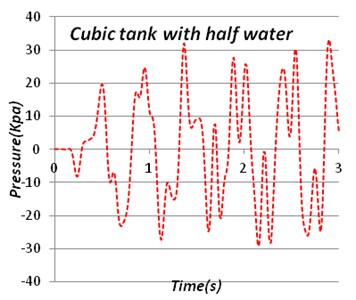
After subjecting accelerogram to models time-displacement diagram and either time-pressure stress diagram can obtain like Fig. 9, 10.
Fig. 9Time-displacement diagram of circular tank and cubic tank
a)
b)
Fig. 10Time-pressure stress diagram of circular tank and cubic tank
a)
b)
8. Models comparison
Buried tank model is imposed to different cases of loadings. Table 5-7 show the results relating to these analyses. In Table 5 there is a comparison between tanks with full water and half full water and in Table 6, 7 there is a comparison between fully buried tanks and half buried tanks.
Table 5Overall comparison of wall pressure stress and maximum displacement in studied models
Maximum displacement (mm) | Wall pressure (KPa) | ||||
Half full | Full | Half full | Full | ||
Circular tank | Helena | 50 | 76 | 59 | 577 |
Northridge | 78 | 112 | 183 | 1026 | |
Tabas | 143 | 175 | 782 | 1780 | |
Cubic tank | Helena | 85 | 96 | 113 | 544 |
Northridge | 101 | 130 | 590 | 1108 | |
Tabas | 149 | 196 | 925 | 1690 | |
Table 6Overall comparison of wall pressure stress in fully buried and half buried models
Wall pressure (KPa) | ||||
Difference percentage | Difference percentage | Difference percentage | ||
Circular tank | Helena | 42 | 34 | 59 |
Northridge | 31 | 126 | 183 | |
Tabas | 18 | 645 | 782 | |
Cubic tank | Helena | 30 | 79 | 113 |
Northridge | 24 | 451 | 590 | |
Tabas | 12 | 810 | 925 | |
Table 7Overall comparison of displacement in fully buried and half buried models
Maximum displacement (mm) | ||||
Difference percentage | Difference percentage | Difference percentage | ||
Circular tank | Helena | –16 | 42 | 50 |
Northridge | –17 | 65 | 78 | |
Tabas | –21 | 113 | 143 | |
Cubic tank | Helena | –9 | 77 | 85 |
Northridge | –12 | 89 | 101 | |
Tabas | +3 | 153 | 149 | |
9. Conclusions
By studying tank model, it was obtained that most displacement has been occurred in Tabas earthquake and minimum displacement has been occurred during Helena earthquake. Quantity of water has a great effect on the wall pressure stress. In other words, the full tank against half full tank has more pressure stress almost 2-10 times. This increases structural stresses around the tank wall in the full tank. On the other hand in half full tank, the stress variations in the concrete tank wall are also increasing. With the soil surrounding the tank, horizontal displacement of tank wall with half water is increasing. On the other hand, the amount of time that tank movement decreases also increased. Thus water in the tank is a special matter and Soil Structure Interaction is a very important problem. In models which are fully buried in soil displacement is less than same models with half buried situation. For example in circular tank in Northridge earthquake maximum displacement decreases 21 % when tank is fully buried. Circular tank models have less displacement than cubic models. Pressure stress in tank walls in cubic ones is almost 10 % up to 100 % more than same models in circular ones.
References
-
Jacobson L. S. Impulsive hydrodynamics of fluid inside a cylindrical tank and of fluid surrounding a cylindrical pier. Bulletin of the Seismological Society of America, Vol. 39, 1949, p. 189-204.
-
Housner G. W. The dynamic behavior of water tanks. Bulletin of the Seismological Society of America, Vol. 53, Issue 2, 1963, p. 381-387.
-
Lysmer J., Kuhlemeyer R. Finite dynamic model for infinite media. Journal of Engineering Mechanics Div. ASCE, Vol. 95, Issue EM4, 1969, p. 859-877.
-
Lysmer J., Wass G. Shear waves in plane infinite structures. Journal of Engieering Mechics Div. ASCE, Vol. 98, Issue EM1, 1972, p. 85-105.
-
Kausel E. Local transmitting boundaries. Journal of Engineering Mechics Div. ASCE, Vol. 114, Issue 6, 1988, p. 1011-1027.
-
Haroun M. A. Dynamic analyses of liquid storage tanks. PhD Thesis, California Institute of Technology, Pasadena, 1979.
-
Zienkiewicz O. C., Taylor R. L. The finite element methods. McGraw Hill, Newyork, Vol. 2, 2000.
-
Bonet J., Wood R. R. Nonlinear continuum mechanics for finite element analysis. Cambridge University Press, 1997.
-
Kramer S. L. Geotechnical earthquake engineering. Prentice Hall, New Jersey, 1966.
-
Helwany S. Applied soil mechanics with ABAQUS applications. John Willey & Sons, Canada, 2007.
-
Lin W. T., Hsieh M. H., Wu Y. Ch., Huang Ch. Ch. Seismic analysis of the condensate storage tank in a nuclear power plant. Journal of Vibroengineering, Vol. 14, Issue 3, 2012, p. 1021-1031.
-
Haroun M. A., Housner G. W. Seismic design of liquid storage tanks. Journal of Techical Councils ASCE, Vol. 107, Issue 1, 1981, p. 191-207.
-
Seleemah A. A., El-Sharkawy M. Seismic response of base isolated liquid storage ground tanks. Ain Shams Engineering Journal, Vol. 2, 2011, p. 33-42.
-
Jankowiak T., Lodygowski T. Identification of parameters of concrete damage plasticity constitutive model. Foundations of Civil and Environmental Engineering, Vol. 6, 2005.
