Abstract
When a train passes the turnouts, its allowed speed and safety are influenced by a key factor, i.e. whether the switch rail of turnout can convert to the ideal position. In recent years, during operation of high-speed turnouts, there have been many problems concerning conversion deviations, such as the switch rail not fitting tightly close together with the stock rail, small gauge between the last traction point and switch rail end, jacking block separating of from the rail waist, etc. Taking No. 30 high speed turnout as an example, a corresponding switch rail conversion model is established on basis of traction conversion mechanism. The influences of such factors as various types of bedplate (different bedplates, different friction coefficient), lateral stiffness of switch rail end, stroke error and performance of fasteners on switching force and deviation are analyzed systematically. The results show that: 1) Sliding friction is changed into rolling friction by setting a roller bedplate. This can decrease the friction so as to reduce the conversion force and deviation of the traction points. 2) When 6 traction points are set, the conversion force and deviation both decease obviously. Thus, it is recommended that the scheme of 6 traction points be adopted. 3) Setting 2.0 mm anti-deformation between the 6th point and the switch rail end can effectively control the deviation so as to meet the 1 mm geometric deviation requirements of high speed turnout.
1. Introduction
The speeding-up of existing railways and construction of high-speed railway indicate that China railway will enter a high-speed era. High-speed turnout is the key equipment of high-speed railway, and the maximum speed of a train passing the turnout reaches 350 km/h. A series of problems during design, manufacturing and maintenance of high-speed turnouts in China need to be solved to ensure the stability, comfort and safety of trains [1].
Conversion deviations are the important factors that affect the wheel-rail dynamic interaction in high speed turnout [2]. During conversion of turnout, the switch machine should provide sufficient force to pull the traction points on rail to corresponding design positions. When the switch is locked, the linear form often can not satisfy the theoretical value in design which may result in a series of problems, such as the switch rail not fitting tightly close together with the stock rail, too small gauge from the last traction point to switch end, the jacking block separating from the rail waist, etc. Therefore, it is necessary to analyze the conversion force and deviation for better guidance of design and development of high-speed turnouts [3, 4].
2. Traction conversion mechanism of turnout
Multi-machine multi-point traction mode and the independent external locking device are applied in China's turnout conversions, nevertheless, a machine with multi-point and the linkage external locking mode are adopted in France. During the operation of turnout, the rails are converted according to the required direction of the train through the connection of action bar and switch machine. When the rails are converted to the due position, the switch or nose rail will be locked by locking device. Under normal condition, only if the total power of the switch machine is sufficient to convert the movable rail and has some surplus can the switch or nose rail be moved to the due position. During conversion, at the traction point the thrust force is exerted to the switch rail and nose rail by the action bar of switch machine, so each traction point produces a given displacement (traction range). The thrust force of each point is the concentrated reaction force of the rail at this point. When the turnout is converted correctly, both the alignment of switch rail, nose rail and gauge within turnout zone meet the design requirement, and the sliced section of non-working side of switch or nose rail closely contacted with stock rail or wing rail and locked.
However, during turnout’s conversion, the friction, inclusion of foreign matter, and conversion irregularity caused by its own structural characteristics can not be ignored. Deficient conversion may cause lateral wheel/rail impact, which is more complicated than vertical impact. Main feature of the lateral impact is the sudden change of wheels’ running direction. The wheels produce lateral impact velocity; besides, the shaking vibration speed changes suddenly and then displacement is produced. Therefore, conversion deviation as an important part in lateral irregularity of turnout must be studied [5-6].
3. Mechanical model for switch rail conversion
Switch rail tip, turnout sleeper, traction point and the jacking block are element nodes of the switch rail. The switch rail is simulated as variable cross-section beam element. Its special structure and such key details as switch rail slicing, position of traction point and stroke are considered; some linear and non-linear factors during the conversion are also considered, such as friction force, tightening reaction force of closely-attached rails, reaction force of jacking block and fastener resistance, etc. Fig. 1 shows the mechanical model of the switch rail conversion [7].
Fig. 1Conversion model of the switch rail

(1) The switch rail only deforms in horizontal plane, and influence of axis force is not considered. Section feature of the sliced segment of switch rail is a quadratic polynomial by least squares method; the section feature of elastic bendable segment is weakened according to actual conditions; the rest is constant. The lateral displacement of switch rail end will bear the lateral force from fasteners, whose lateral stiffness is simulated as a linear spring with an elastic coefficient. The lateral stiffness of fasteners at the switch end becomes big, so it is assumed as a rigid fixed end.
(2) The friction of sliding bedplate is a concentration force acted on the switch rail's nodes, and its direction is always converse to that of the rail movement. It is proportional to the weight of the rail supported by the sliding bedplate, not varying with the displacement of switch rail. When rollers structure is adopted in bedplate, the friction force equals to vertical bearing load multiplied by rolling friction coefficient of the rollers and varies with the different positions of the switch rail during conversion. The parts of switch rail which are not lifted by the rollers are still supported by the sliding bedplate.
(3) The tight contact between the stock rail and switch rail, the interaction between jacking block and switch rail waist are considered as non-linear spring contact. The elasticity coefficients of these contacts are the lateral stiffness of the stock rail and jacking block, their reaction forces are and respectively.
(4) The initiate state is the switch rail tightly close together with the stock rail. After actual conversion, the switch rail can not overlap its origin linear at the initial state, so its deviation is produced, i.e. the gap between the two rails.
4. Mechanical model for nose rail conversion
Special structure of frog and the linear and nonlinear factors of conversion are considered in mechanical model for nose rail conversion. The positions of nose rail's tip, turnout sleeper, traction point, jacking block and spacer block all correspond to the element nodes of nose rail. Linear forms of nose rail and wing rail are simulated by restricting their node coordinates located on the curve state. In this model, fastener and the spacer block before the fixed end are simulated by spring element. The nose rail, wing rail, and spacer block at the frog end are simulated by nonuniform beam elements. The tight contact between the nose rail and wing rail and the jacking block are simulated by nonlinear spring. Fig. 2 shows the calculation model of nose rail.
Fig. 2Conversion mechanical model of single-limb bendable nose rail

The model can calculate the conversion of multiple nose rails with various initial states by changing model parameters. The specific assumptions of the model are as follows:
(1) The wing rail and fasteners function during conversion. Behind 7 sleeper spacings of the nose rail end, the lateral and longitudinal restriction of fasteners and spacer block become stronger, so it is assumed as a rigid fixed end. The compression, elongation and deflection of nose rails and jacking block between nose rail and wing rail, as well as the axial compression of spacing block are considered.
(2) The nose rails transverse bending deformation occurs in the horizontal plane, and the effects of axial force and axial deformation are considered. Section properties of the nose rail sliced segment is fitting as a quadratic polynomial through the least squares method. Bendable segment can be weakened according to the actual situation, and the section properties of the rest segments are constants. The lateral stiffness of frog end is simulated as a linear spring with an elastic coefficient . The lateral resistance , is the lateral displacement of fasteners.
(3) The surface of sliding bedplate is tightly contacted with the underside of rail, and they are in the same plane. The friction of sliding bedplate is assumed as the concentrated force acted on the nodes of nose rail at the sleepers. Its direction is constantly contrary to the movement direction of nose rail, and is directly proportional to the supporting force of the sliding bedplate. It does not vary with the displacement of nose rail. It is assumed that the supporting force of one sliding bedplate is , and its friction is . is the friction coefficient.
(4) It is assumed that the nose rail converts from normal-position to anti-position in the absence of friction, closely-attached effect and transverse flexural rigidity at the fixed point of its end, the linear form of nose rail after conversion is an ideal state . If there are such linear and nonlinear factors as friction, closely-attached effect of rails, jacking block supporting effect and fastener resistance, etc, the linear form after conversion is . The space between the two positions is the nose rail conversion deviation , is the deviation at the node .
(5) The closely-attached effect between the wing rail and nose rail, the action of jacking block withstanding the waist of nose rail waist are considered as non-linear spring. The elasticity coefficients of these contacts are the lateral stiffness of the stock rail and jacking block. When the jacking block is set at nose rail node , if it does not contact with nose rail, , its force is zero; if it contacts with nose rail, it is assumed as a spring with stiffness , and its force is . is the distance between nose rail waist and jacking block. The calculation of closely-attached force is the same as the reaction force of jacking block.
5. Calculation parameters
5.1. Switch rail part
Movable part of switch rail of No. 30 turnout is 28345 mm long; the sliced segment is 12188 mm long; rail 60D40 is adopted, the rail top slope is 1:40; cross-sectional area of entire section of switch rail is 8.918×103 mm2; moment of inertia is 7.563×106 mm4. The weight of external locking device is 40 kg. The lateral stiffness of fastener is 50 MN/m, the spring stiffness of the tightness between rails and jacking block are 10 kN. Vertical support stiffness of sliding bedplate under the switch rail is 100 MN/m. The fastening force of fastener II is 10 kN. During the conversion of switch rail, the non-tight part of switch rail moves 0.375 stroke firstly, and then other traction points are in place at the same time [8].
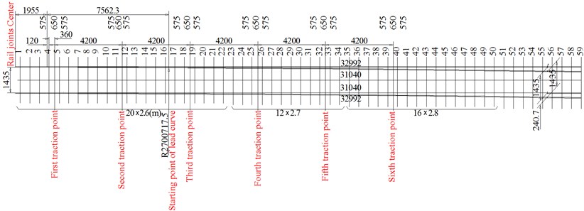
There are 6 traction points on the switch rail: the first is 480 mm away from the switch rail tip; from point 1 to point 6, the distance between every two points is 4200 mm; the sixth is 6865 mm away from switch rail end; their strokes are 160 mm, 136 mm, 112 mm, 88 mm, 64 mm, and 39 mm respectively. The layout of traction points is shown in Fig. 3.
Fig. 3Traction points layout of switch rail
In Sep. 2007, MOE Key Laboratory of High-speed Railway Engineering of Southwest Jiaotong University tested friction coefficient of the sliding bedplate and Roller bedplate of high speed turnout. There were 5 kinds of vertical load on the sliding bedplate surface and roller structure: 1) weight of 26 kg rail; 2) rail and 1 channel steel (total weight of 41.5 kg); 3) rail+2 channel steels (total weight of 57 kg); 4) rail+2 channel steels (weight of 70 kg); 5) rail+2 channel steels+2 weights (total weight of 83 kg). The follow results were obtained from the test [9].
The sliding bedplate surface condition: the friction coefficient changes in range 0.153~0.191 when not oiled, with an average value 0.177; the friction coefficient changes in range 0.107~0.148 when oiled, with an average of 0.123. Raising the bedplate for elevation of 10 mm: the non-oiled coefficient changes in range 0.196~0.210, with an average value 0.200; the coefficient changes in range 0.128~0.155 when oiled, with an average of 0.143. The friction during conversion can be reduced when the sliding bedplate is oiled, while it may be increased if the baseplate is tilted or set a slope or with rough surface. The friction coefficient of sliding bedplate is set as 0.25 to ensure the reliability of calculation.
The rollers are raised for the same height: the friction coefficient changes in range 0.044~0.069, with an average of 0.053; if two wheels are raised for different height, the friction coefficient changes in range 0.054~0.094, with an average of 0.074. When the one is higher than the other, the lateral load will increase under the vertical load, which means the friction coefficient is increased. The friction coefficient of roller bedplate is a constant, and it is set as 0.10.
5.2. Nose rail part
Single-limb bendable nose rail is adopted to Chinese 30# turnout. The frog angle is 1.909º. Frog end adopts fasteners II, and the lateral supporting stiffness of the fastener is 50 MN/m. The spring stiffness of closely-attached effect and jacking block is 100 MN/m. The spacer block before the fixed end of the nose rail is simulated as a linear spring element (200 MN/m). The cross-sectional area of the spacer block at nose rail end is 10000 mm2 and its moment of inertia is 10000000 mm4.
At the movable part of frog (13825 mm long), the long and short nose rails are connected by spacer block and bolt. The nose rail adopts 60D40, and there is a rail top slope (1:40), with cross-sectional area 8918 mm2, moment of inertia 7563000 mm4. The stock rail adopts ordinary rail CHN60, with cross-sectional area 7745 mm2, moment of inertia 5240000 mm4.
Fig. 4Traction points layout of the nose rail
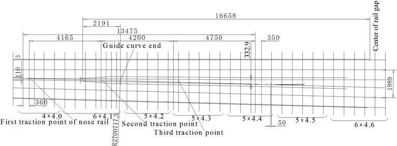
There are 3 traction points on nose rail. The first is 360 mm from the throat, and the third is 5100 mm from the fixed position of nose rail. The distance between each traction is 4165 mm and 4200 mm respectively. According to the stroke of the first traction point and the elastic bendable center position of nose rail, the stroke of each traction point is 110 mm, 76 mm, 42 mm respectively. The layout of traction points is shown in Fig. 4.
6. Analysis of conversion and its deviation of switch rail
6.1. Adopting ordinary sliding bedplate
When the ordinary sliding bedplates are applied, the traction forces and conversion deviations are calculated by adopting conversion simulation model of the switch rail. Table 1 shows the results.
As shown in Table 1 and Fig. 5, the maximum traction force appears at the 6th traction point, 5167.2 N; the traction forces of all traction forces are within allowable range (≦6000 N). The friction during conversion can be reduced by using antifriction sliding bedplate, so as to reduce the traction force.
Fig. 6 shows how the conversion deviation varies with different friction coefficient. The maximum 2.73 mm appears between the 6th traction point and the switch end. The conversion deviation increases linearly with the increase of sliding bedplate friction coefficient, and it can be reduced by adopting antifriction measures.
Table 1Maximum pulling force and conversion deviation of each traction point of switch rail
(mm) | |||||||
0.00 | 0.1 | 0.5 | 2.2 | 8.8 | 163.6 | 622.4 | 0.00 |
0.05 | 156.6 | 235.5 | 240.4 | 321.2 | 302.9 | 1365.2 | 0.55 |
0.10 | 313.2 | 470.8 | 482.2 | 637.4 | 522.5 | 2341.4 | 1.09 |
0.15 | 469.8 | 706.0 | 724.0 | 953.5 | 743.5 | 3317.7 | 1.64 |
0.20 | 626.4 | 941.2 | 965.9 | 1267.3 | 964.4 | 4289.9 | 2.18 |
0.25 | 783.1 | 1175.8 | 1210.7 | 1571.7 | 1188.5 | 5167.2 | 2.73 |
Note: is the baseplate friction coefficient; is the switching force of ; is maximal insufficient displacement. | |||||||
Fig. 5Conversion force distribution of the traction points
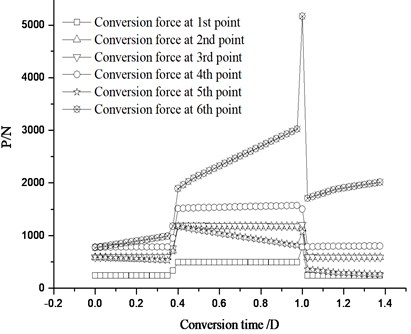
Fig. 6Variation of conversion deviation with different friction coefficient
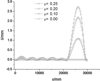
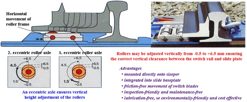
Fig. 7Working principle of roller bedplate
6.2. Adopting roller bedplate
The rollers have no effect when the switch rail tightly closes to the stock rail. When the switch rail departs from the stock rail, the rollers begin to contact with the switch rail base, and gradually raise the switch rail up. And then the sliding friction is changed into rolling friction, which greatly reduces the friction resistance. The position and height of the rollers can be adjusted to ensure the best work condition at different positions. The working principle is shown in Fig. 7 [10].
After the bedplate with rollers is set, the movable part of the switch rail can mostly be lifted during its movement, and the friction is reduced, therefore the resistance during conversion process is reduced. There is relation between the friction of the roller bedplate structure and the raise amount of the rollers. When the switch rail closely nestles to the stock rail, there is almost no raise amount.
6.3. Vertical height adjustment of the rollers
Based on above-mentioned design scheme (6 traction points), the rollers are adopted in bedplate structure. During the conversion movement of switch rail, the vertical force on the rollers or bedplate is changing. There are 8 roller bedplates for each switch rail, and the distance between roller bedplates is 6 sleeper spacings. According to analysis of vertical force on the switch rail, the vertical forces of the rollers and bedplate at different conversion stages can be obtained. The vertical force multiplied by the corresponding friction coefficient is the friction force, which is input to the simulation model as the initial parameter for further calculation. The corresponding calculation results are shown in Fig. 8 and Fig. 9.
Fig. 8Conversion force under the height adjustment of roller
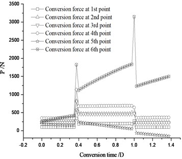
Fig. 9Conversion deviation under the height adjustment of roller
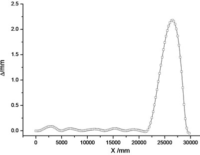
As shown in Fig. 8, when the rollers are applied in bedplate structure, the maximal conversion forces of each traction point are 343.3, 824.6, 818.1, 1134.2, 576.4 and 3146.0 N – all within allowable power value of the switch machine. Fig. 7 shows that the state of switch rail close together with stock rail is in good condition; the maximal conversion deviation 2.18 mm appears between the 6th traction point and switch rail end, and it's necessary to set 2.0 mm conversion deformation of switch rail.
The conversion force of traction point is related to the friction coefficient of the roller bedplate, so it can be effectively decreased by reducing the friction coefficient. The needed conversion force when switch rail close together with stock rail is bigger than whose switch rail separated from stock rail, because in addition to overcome the lateral stiffness of switch rail itself and friction of bedplate, the needed conversion force is also increased by the closely-attached effect and jacking block reaction.
6.4. Integrated friction coefficient
In calculation of friction coefficient (when the rollers are set) by French Vossloh Cogifer, the friction coefficient of rollers and bedplate is integrated as 0.20 instead of separate calculation. Fig. 10 and Fig. 11 show the calculation results after adopting the integrated friction coefficient applied in No. 30 turnout.
As shown in Fig. 10, the maximal conversion force of each traction point is 626.4, 941.2, 965.9, 1267.3, 964.4, 4289.9 N respectively, all within the allowable power range (≦ 6000 N) of the switch machine.
In Fig. 11, the state of switch rail close together with stock rail is in good condition, conversion deviation of each traction point are all < 0.5 mm, and the maximum 2.18 mm appears between the 6th point and switch rail end, so it is necessary to set a conversion deformation of 2.0 mm.
Fig. 10Distribution of conversion force
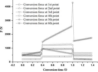
Fig. 11Distribution of switch rail conversion deviation
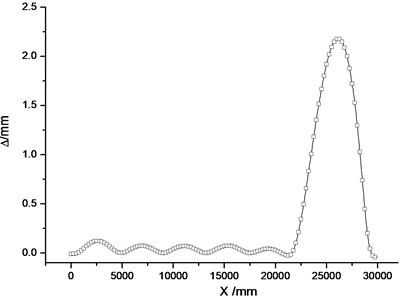
The conversion force and deviation of switch rail during conversion process can be reduced by adopting roller bedplate. When 6 traction points are set, a conversion deformation of 2.0 mm is set between 6th point and switch rail end to make the deviation meet the requirement of high speed turnout. The integrated friction coefficient 0.20 is adopted in the following calculations.
6.5. Influence of lateral stiffness of switch rail end
6.6. Lateral stiffness change of fastener
The displacement restrictor structure is applied on the switch rail end. The lateral support stiffness of II fastener is 50 MN/m. Variation of conversion deviation and force are calculated under influences of different lateral stiffness of switch rail end. The results are shown in Table 2.
In Table 2, in the 1st column is the ratio of fastener's lateral stiffness to original lateral stiffness (50 MN/m): 0.1, 0.5 and 2.0 denote the lateral stiffness of fastener 5 MN/m, 25 MN/m and 100 MN/m.
Table 2The maximal conversion force and deviation (N)
0.1 | 626.5 | 942.2 | 968.1 | 1287.3 | 837.5 | 5124.0 | 9785.7 | 3.49 |
0.5 | 626.4 | 941.4 | 966.4 | 1271.3 | 933.5 | 4460.6 | 9199.6 | 2.43 |
1.0 | 626.4 | 941.2 | 965.9 | 1267.3 | 964.4 | 4289.9 | 9055.1 | 2.18 |
1.5 | 626.4 | 941.1 | 966.1 | 1265.6 | 977.5 | 4201.1 | 8977.8 | 2.07 |
2.0 | 626.4 | 941.0 | 966.3 | 1263.7 | 985.6 | 4146.6 | 8929.6 | 2.01 |
The fastening effect of fastener at the switch rail end may cause increasing of friction, while the increasing of switch rail end lateral stiffness may eliminate more friction. As the fastener stiffness increases, the switching force of 5th traction point increase a little, but the 6th decreases a bit, and the rest basically unchanged.
The conversion deviation decreases as the lateral stiffness of the switch rail end increases. Thus, under the premise that the conversion force meets the requirement of switch machine power, increasing of lateral stiffness (no weak section, increasing fastener stiffness, setting of spacer block, etc.) is favorable to control of deviation so as to maintain the ideal linear form of the switch rail after conversion.
6.7. Adoption of Spacer Block
Displacement restrictor or spacer block is adopted for turnout switch rail on China's high speed railway turnout, and the setting of spacer block can effectively increase the lateral stiffness of the switch end. It is necessary to analyze the conversion of switch rail when the spacer block is adopted. In calculation, the spacer block is a linear spring of 200 MN/m. The results are displayed in Fig. 12 and Fig. 13.
Fig. 12The maximum traction force for different end structures of switch rail
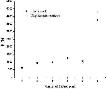
Fig. 13The conversion deviation for different end structures of switch rail
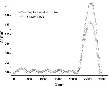
As shown in Fig. 12, when the spacer block is set, the conversion force at the 6th traction point presents obvious trend of decrease. The reason lies in that the setting of spacer block increases the lateral bearing stiffness to prevent the transfer of friction resistance and provide great rebound for the switch rail. Fig. 13 shows the comparison of conversion deviation under the two schemes (setting spacer block or displacement restrictor). When the spacer block is set, the deviation decreases from 2.18 mm to 1.58 mm. The stronger the constraints of switch rail end are, the smaller the deviation becomes.
6.8. Influence of stroke deviation
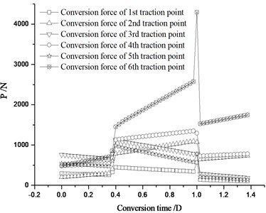
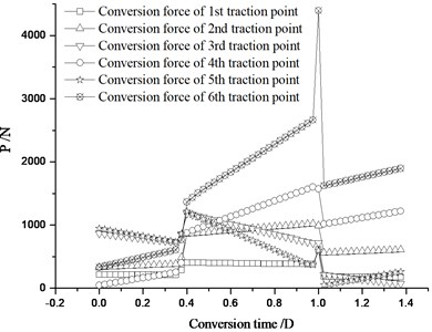
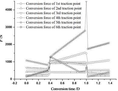
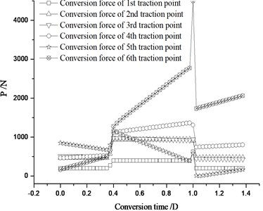
When the equipments of the switch rail are installed, there may be certain size deviations, which lead to the change of the traction point’s stroke. In calculation, the deviation limited value is 2.0 mm, and the stroke of each traction point is increased or reduced by 2.0 mm in analysis. During conversion process, each traction point moves according to the same stroke proportion and reaches the place simultaneously. Table 3 shows the calculation results of conversion force.
As shown in Table 3, the conversion force changes great when the 5th stroke is reduced by 2 mm or the 6th stroke is increased by 2 mm. The maximum is within the allowable range of traction power of switch machine. During installation or test of the switch machine, the stroke of traction points should be strictly controlled to prevent large conversion forces.
Table 3Maximal conversion force for each traction point under different stroke deviations
Stroke deviations | |||||||
Constant | 626.4 | 941.2 | 965.9 | 1267.3 | 964.4 | 4289.9 | 9055.1 |
651.3 | 990.9 | 1008.4 | 1255.6 | 961.2 | 4289.1 | 9156.5 | |
601.5 | 994.0 | 995.1 | 1279.0 | 967.6 | 4290.8 | 9128.1 | |
568.9 | 1094.7 | 1118.5 | 1346.6 | 986.3 | 4295.6 | 9410.7 | |
683.9 | 1091.6 | 1142.5 | 1289.8 | 942.5 | 4284.2 | 9434.5 | |
668.9 | 1100.5 | 1260.6 | 1438.5 | 911.3 | 4263.7 | 9643.5 | |
584.0 | 1103.6 | 1227.2 | 1495.4 | 1064.7 | 4316.1 | 9791.0 | |
613.7 | 1020.4 | 1184.0 | 1600.0 | 1216.0 | 4394.8 | 10028.8 | |
639.1 | 1017.3 | 1213.9 | 1542.6 | 1078.3 | 4185.1 | 9676.2 | |
630.0 | 960.0 | 1075.6 | 1462.8 | 1166.6 | 4055.0 | 9350.0 | |
622.9 | 963.2 | 1056.4 | 1522.0 | 1291.2 | 4509.2 | 9965.0 | |
625.6 | 946.3 | 978.9 | 1361.4 | 1161.3 | 4498.1 | 9571.5 | |
627.3 | 943.0 | 992.1 | 1301.6 | 1036.5 | 4042.2 | 8942.7 | |
Note: is the stroke of the point on switch rail, is the increase of stroke at point by 2 mm, is the reduction of stroke at point by 2 mm. | |||||||
Fig. 14The conversion force distribution of each traction point under stroke change
a) The 2nd stroke increased by 2 mm
b) The 4th stroke increased by 2 mm
c) The 5th stroke reduced by 2 mm
d) The 6th stroke increased by 2 mm
6.9. Influences of fastening state of fasteners
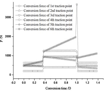
The straight and curve switch rail can be closely attached to the stock rail in design, so the fasteners at the switch rail end should be tightened in closely-attached state. If the fasteners at the straight switch rail end is tightened under normal condition, while the ones at the curve switch rail end is tightened during the switch rail separated from the stock rail, the conversion state of the whole switch rail will be changed. Fig. 15 shows the conversion forces of each traction point.
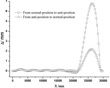
Fig. 15 shows the conversion force reaches its peak at closely-attached state. In Fig. 16, the maximal conversion force from normal-position to anti-position is 5248.1 N, which is far bigger than that from anti-position to normal-position 3671.5 N. The reason is that when the curve switch rail closely attached to the stock rail, in addition to overcoming the attached resistance, jacking block reaction force and friction force, a great deal of elastic deformation energy is still need to overcome. Fig. 17 shows, the maximal conversion deviation from normal-position to anti-position is 6.79 mm, which is much bigger than that from anti-position to normal-position 2.18 mm. This is due to the big deviation produced by the switch rail itself. It is obvious that it is favorable to control of conversion force and deviation to tightened the fastener at the switch rail end when the straight and curve switch rail is in the closely-attached state.
Fig. 15Conversion forces (fastener at the curve switch rail end is tightened during the switch rail separated from the stock rail)
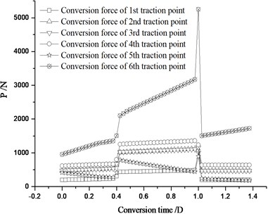
a) From normal-position to anti-position
b) From anti-position to normal-position
Fig. 16Distribution of maximal conversion forces (fastener at the curve switch rail end is tightened during the switch rail separated from the stock rail)
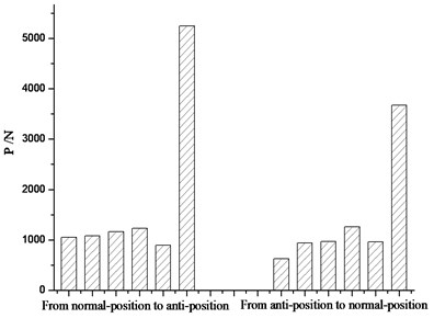
Fig. 17Distribution of conversion deviations (fastener at the curve switch rail end is tightened during the switch rail separated from the stock rail)
7. Influence of sliding bedplate friction on the conversion and its deviation of nose rail
The initial state of nose rail (Chinese 30# turnout) is that the train passes the turnout from main line, when it convert from normal-position to anti-position, there will be plenty of bending deformation energy produced within nose rail, so the conversion force will be big. When it converts from anti-position to normal position, the bending energy will be released, so the conversion force will be smaller. Table 4 shows the maximum conversion forces of each point during conversion under different friction coefficients. Fig. 18 shows the conversion force distribution after two conversions.
When the friction coefficient of sliding bedplate is 0.25, the maximum conversion force of each traction point is 327.2 N, 2288.1 N, and 4578.2 N respectively. They are all within the output power of switch machine 6000 N. The conversion force of the third traction point is bigger than the rest two, so it is a controlling point.
Table 4Maximum conversion force and deviation under different friction coefficients (N)
Conversion direction | (mm) | |||||
From normal-position to anti-position | 0.25 | 327.2 | 2288.1 | 4578.2 | 7193.5 | 0.43 |
0.20 | 284.9 | 2075.2 | 4097.7 | 6457.8 | 0.35 | |
0.10 | 202.1 | 1648.3 | 3136.9 | 4987.3 | 0.18 | |
0.00 | 123.1 | 1331.1 | 2173.6 | 3627.8 | 0.00 | |
From anti-position to normal position | 0.25 | 270.3 | 1204.8 | 2651.6 | 4126.7 | 0.43 |
0.20 | 216.2 | 963.8 | 2121.3 | 3301.3 | 0.35 | |
0.10 | 108.1 | 481.9 | 1060.6 | 1650.7 | 0.18 | |
0.00 | 0.0 | 0.0 | 0.0 | 0.0 | 0.00 |
Fig. 18Conversion deviation distribution of nose rail
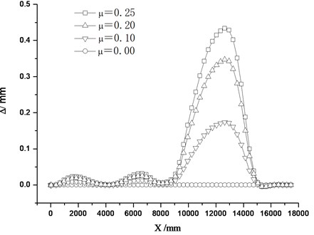
The conversion deviation of nose rail decreases as the friction coefficient of sliding bed plate decreases. When the coefficient is 0.25, the deviation is 0.43 mm; when the coefficient is 0, the deviation is reduced to 0. Therefore, friction force is the main factor to cause conversion deviation, so measures should be taken to reduce friction. The displacement of each traction point is controlled to ensure the reasonable linear form of nose rail after the conversion so as to satisfy the conversion precision requirement of high-speed railway turnout.
8. Conclusions
There are 6 traction points on the switch rail for No. 30 turnout. When the ordinary sliding bedplate is adopted, the maximal conversion force of the traction points is 5167.2 N (within the range of the switch machine's power), which can meet the requirements. When the state of switch rail close together with stock rail in good condition, the maximum conversion deviation is 2.73 mm, appearing between the 6th point and the switch end. The deviations of switch rail are too large to meet the requirement (1.0 mm) of high speed railway turnout, so certain measures should be taken to solve this problem.
When the roller bedplate is applied, the sliding friction is changed into rolling friction. So the friction is reduced and the conversion force and deviation can be reduced effectively. After the setting of rollers, the maximum deviation is 2.18 mm, appearing between the 6th point and the switch end. Setting 2.0 mm anti-deformation between the 6th point and the switch rail end can effectively control the deviation so as to meet the requirements of high speed turnout.
When 6 traction points are set, the conversion forces and deviations both decease obviously. Therefore, it is suggested that the scheme of 6 traction points be adopted. Besides, the turnout components should be installed in accordance with procedures. The fastener at the switch end should be tightened when the straight and curve switch rail in the closely-attached state. The linear form of switch rail after conversion can be effectively controlled by increasing the lateral stiffness of end structure (setting spacer block, increasing lateral stiffness of fasteners), moving forward the fixed segment, etc.
It is suggested that 3 traction points be set on nose rail of 30# turnout, and the distance be 4165 mm and 4200 mm; distance between the third traction point and nose rail fixed end is 5100 mm; the strokes are 110 mm, 76 mm and 42 mm respectively.
References
-
R. Chen. Theory and Application of Vehicle-Turnout-Bridge Coupling Vibration in High Speed Railway. Ph. D. Thesis, Southwest Jiaotong University, 2009.
-
R. Chen, P. Wang, X. K. Wei. Influence of conversion deviation on dynamic performance of high-speed railway turnout. Key Engineering Materials, Vols. 474-476, 2011, p. 1599-1604.
-
Y. F. Xu. Causes and rectification of conversion deviation of straight switch rail in common single turnout. Shanghai Railway Science and Technology, No. 2, 1998, p. 27-28.
-
P. Wang, R. Chen, X. P. Chen. Key technologies in high-speed railway turnout design. Journal of Southwest Jiaotong University, Vol. 45, No. 1, 2010, p. 28-33.
-
X. P. Cai, C. H. Li. Study on controlling the switching force and scant displacement of the point rail of the high speed turnout. Journal of the China Railway Society, Vol. 30, 2008, p. 48-51.
-
P. Wang. Calculation and analysis of conversion forces of multi-point traction turnout. Railway Standard Design, No. 2, 2002, p. 23-25.
-
P. Wang, R. Chen. Control circuit analysis and conversion calculation of electric switch machine of high speed railway turnout. Przegląd Elektrotechniczny (Electrical Review), Vol. 88, No. 1b, 2012, p. 52-56.
-
P. Wang. Design Theory and Practice of High Speed Railway Turnout. Chengdu: Southwest Jiaotong University Press, 2001.
-
X. P. Cai, C. H. Li, P. Wang. Effect on the scant displacement of switch rail induced by friction of slide baseplate. China Railway Science, Vol. 28, No. 1, 2007, p. 8-12.
-
Pavel Vrsecky, Jiri Walter. Switch Blade Rolling Device. US5628480 A, 1997-5-13.
About this article
This work is financially supported by the National Natural Science Foundation of China under Grant No. 51078320 and No. 51008256. And it was also supported by Scientific Research and Development Program of Chinese Ministry of Railways under Grant No. 2011G009.
