Abstract
Vibration in the chip production process greatly limits the devices’working efficiency. There is a strong need to develop an optimization method to improve the structure vibrostabilization. In this paper, we studied an LED sorting arm and optimization the sorting arm in three steps. Firstly, a series of experiment are carried out to optimize the particle damping capsule distributionand filling ratio. Then, an improved level set optimization algorithm is adopted to carry out the shape and topology optimization of the arm with a damping capsule at the same time. At last, the virtual and real tests are carried out on three arms, the results proved that our optimize method can effectively suppress the vibration.
1. Introduction
The rigid growth of technology in semiconductor has greatly increased the demand for chips. However, the vibration in chip manufacture device has greatly limited the efficiency of production. Take the LED chip sorting and packaging equipment for example, its working step is: (1) rotating to position; (2) waiting for the vibration weakened; (3) pick up the chip. If the amplitude of the vibration is bigger than 30 μm the operation fails. Table 1 shows the result of a beat experiment carried out on LED sorting equipment. We can see that the equipment spends 31.3 % of working time waiting for arm vibration suppression to ensure the success rate up to 99.5 %. Improving the vibration resistance of arm structure is the direct way to improve equipment efficiency.
Table 1Beat experiment of LED sorting equipment.
Groups | Rotating time (ms) | Nozzle delay time (ms) | Success rate |
1 | 83 | 100 | 99.95 % |
2 | 83 | 70 | 99.5 % |
3 | 83 | 40 | 99 % |
4 | 83 | 20 | 85 % |
5 | 83 | 10 | 28 % |
Based on the structural dynamics theory, improve the damping ratio will accelerate vibration attenuation, and raise the dynamic stiffness will reduce the amplitude. As we observed in high-speed camera the vibration in vertical direction is eliminated quickly after the arm touches chips wafer, the vibration in horizontal direction is the main reason for sorting failure.
The optimization should carry out in the following two steps:
(1) Increasing the structure damping ratio;
(2) Improve the dynamic stiffness of the structure.
There are many active vibration suppression and passive vibration suppression methods developed by scholars. Compared to each other, the passive vibration suppression method is widely used in chip production equipment for lower cost and easier to maintain. In this paper, the particle damping structure is chosen to raise the arm structure damping ratio. Particle impact damping is an effective vibratory energy dissipation structure [1]. In 1999, R. D. Friend [2-4] studied the particle damping structure on a cantileveled aluminum beam, and he found the maximum specific damping capacity of particle damping is about 50 %, which is more than one order of magnitude higher than the intrinsic material damping of a majority of structural metals (1 %). Mao [5] proposes that under the right conditions, particle damping can reduce 60 % of the original vibration time. The damping ratio changes under different conditions. K. S. Marhadi [6] did a series of experiment to discuss the influence of mass ratio, material, and shape to particle damping. Chan K. W. [7] did a series of experiment on particle damping to find out the influence of materials, particle sizes, loading ratio on particle damping. They have discussed almost every parameter on particle damping, but they missed the influence of the distribution of damping capsule to the damping ratio, which will be discussed in this paper. We choose the best damping structure from eight designs.
On the other hand, we need to improve the dynamic stiffness of sorting arm. As the size of the arm isn’t the design parameter, the shape optimization and topology optimization are needed to carry out on the arm. However, the element-based optimization method is difficult to be combined with the shape and size optimization. Moreover, the boundary result of the conceptual design is usually identified with zigzag features [8, 9]. In 2000, Sethian and Wiegmann [10] are among the first researchers to extend the level set method devised by Osher and Sethian [11] into structural topology optimization. The level set method is a potential and appealing method based on the moving implicit boundaries, and is further developed as a nature set to combine the structural topology and shape optimization synthetically in [12, 13]. But the classical level set does not solve the inherent problem of ill-posedness of shape optimization [14], it means the classical level set method cannot create new holes in the middle of a shape, and the initial design will has great influence on result of optimization. In this paper, we improved the level set method by adopting CS-RBFs with C2 smoothness to interpolate the level set function, and convert the classical level set methods into a parameterized level set method for topology and shape optimization.
After the damping design and structure optimization, the virtual and real tests are carried out on the model. The design procedures are shown in Fig. 1.
Fig. 1Integrated optimization method

2. Damping design
In this paper, particle damping is installed on the arm of LED sorting equipment to eliminate vibration energy. From the work of Chan and Marhadi, we can get the following rules: (1) the best material of particles is tungsten (chosen from tungsten, aluminum, ABS particles); (2) 1:10 is the best proportion between particle size and container size; (3) filling ratio of 70 %-90 % can achieve the best damping effect in most conditions; (4) damping installation at the position with the largest amplitude has the best vibration suppression effect. This paper carries on further impact experiments to research the distributing of the particle damping in more detail. The experiment takes out on the arm shown in Fig. 2.
Fig. 2Classic arm structure

When the end of the aluminum arm is fixed, the first four modes of the arm are shown in Fig. 3. We can predict that when vibration happens, the front location (modal 1, 2, 4) or the middle (mode 1, 3) will have the largest amplitude. Based on the rule (4), the damping will be installed at the front and middle.
Fig. 3The first four modes of LED sorting arm
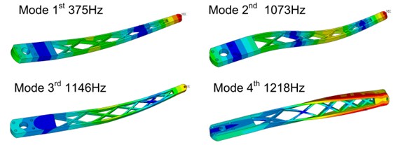
Fig. 4Test equipment installation and arm fixture method
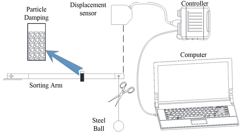
The test platform is shown in Fig. 4. A steel ball is hanging at the front of the arm through a rope. The mass of the steel ball affects the quality of excitation directly. A light steel ball can’t from an effective excitation; on the other hand, a heavy steel ball will lead to plastic deformation of the arm. We calculated the equivalent impact force of the arm with acceleration, then, we chose the steel ball with the gravity equal to the equivalent impact force of the arm. When we cut off the rope, an impact excitation is produced; then, we get the displacement data from laser displacement sensor installed at the front of the arm and process it in a computer.
There were two kinds of damping capsules used in the experiment. They were designed in cylindrical and all made of aluminum, as shown in Fig. 5. Both of the damping capsules are 9 mm in inner diameter with 0.5 mm wall thickness. The longer capsule fixed horizontally on the arm was 40 mm in length, 1.5 g in weight; the shorter capsules fixed vertically on both sides of the arm were 20 mm in length, 0.75 g in weight. The first-order natural frequency of the longer damping capsule was 19891 Hz, which were much higher than the excitation frequency.
Fig. 5Damping capsules
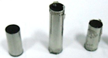
Fig. 6Damping capsule distribution
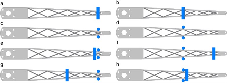
Fig. 7Damping ratio of different damping distribution and filling ratio
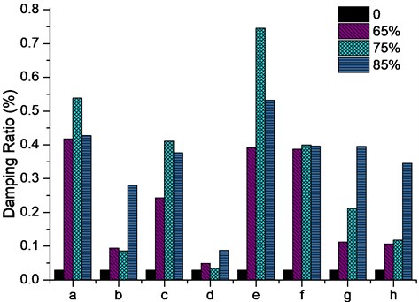
The arm is fixed in two positions to get horizontal and vertical impact test. As we known, too many particles at the front will raise the initial amplitude of the arm. So, we set the maximum particle weight accounted for 10 % of the weight of the arm. The particles are filled in damping capsules with filling ratio of 0 %, 65 %, 75 %, 85 %; then, the capsules are fixed in different positions of the arm. Eight sets of particle damping distribution have been discussed in this paper as shown in Fig. 6. The blue areas on the arms are the damping capsules. The test results are shown in Fig. 7.
The vibration suppression effect varies with the filling ratio and distribution. We can get the conclusion from the results: particle damping installed in the front of arm can achieve the greatest effect of vibration suppression, and in most situations, 75 % – 85 % filling ratio has the best vibration suppression effect. The best result is 75 % filling ratio at e distribution.
3. Structural optimization
3.1. Optimization objectives
Based on the dynamic theory, the dynamic stiffness equation of single freedom system is:
where is the exciting force; is the amplitude; is the static stiffness; is the frequency ratio, and ( is the exciting frequency, is the natural frequency); is the damping ratio.
In the forced vibration conditions, the dynamic stiffness curve is divided into three regions: quasi-static region , resonance region and inertia region . The sorting arm working is obviously in the quasi-static region. The dynamic stiffness in the quasi-static region is:
Raise the first natural frequency and static stiffness will ascend the dynamic stiffness effectively.
3.2. Parameterization level set topology optimization
In the classic level set topology optimization method, the shape in a reference domain is represented as a Lipchitz continuous level set function . For instance, the 3D structure is expressed as follows:
where is the spatial variable, is the pseudo-time. The optimal solution of the level set function is obtained through the Hamilton-Jacobi equation:
where is the normal velocity. The procedure of optimization is to find a proper to drive the solution of Hamilton-Jacobi equation. The classical level set method costs time and lies in the initial conditions.
In this paper, a popularly studied family of CS-RBFs with smoothness is adopted to interpolate the level set function, which can be expressed as follows:
where is the radius of support. By using the CS-RBFs, the level set function can be interpolated at their pre-specified knots over the whole design domain, as:
where are the shape functions, and the expansion coefficient vector is .
By substituting equation (6) into the Hamilton-Jacobi PDE equation (4), the space and time of the original PDE is now thoroughly separated, yields:
Hereto, the original discrete level set shape optimization method is now converted into a parameterized level set method for topology and shape optimization. In this way, the location of the particle damping and structure of arms can be optimized at the same time.
The stiffness optimization model can be expressed as:
where is the objective function, is the number of the design variables , the inequality is simply the volume constraint. Bound constraints and of are used for OC. is the level set method; Heaviside function and its derivatives Dirac function is used as follows:
The linearly elastic equilibrium equation is written in its weak variant form as:
where denotes the energy bilinear form, and is the load linear form. is the kinematically admissible set of displacements while denotes the virtual displacement field belonging to , and is the displacement field. is the elasticity tensor, is the strain field, the traction is only defined over the traction boundary, is the body forces, and is the prescribed displacement on the admissible Dirichlet boundary.
The natural frequency optimization model is:
where are the given weighting coefficients, which are corresponding to the first optimized frequencies . The weak form of the eigenvalue problem for the -th eigenvalue is given by:
where is the model shape corresponding to ; is an arbitrary function which satisfies the kinematic boundary conditions; is the space of kinematically admissible displacement fields.
The bilinear forms and are defined as:
where denotes the density of the material. The meanings of other parameters are consistent with the static stiffness optimization.
By using the material derivative method and the adjoint equation, the result of sensitivity analysis can be obtained:
The strain energy density in the stiffness optimization model is:
The strain energy density in the natural frequency optimization model is:
where is a positive Lagrange multiplier.
3.3. Optimization with damping structure
As we discussed in sections before the horizontal direction dynamic stiffness is very important for the sorting arm, thus, the optimization is taken in the horizontal cross section, and the particle damping is installed at the front of the arm. The optimization objective is to raise the first-order frequency and static stiffness.
The constraints of the optimization are:
1. A rigid area is added at the front of the design region to substitute the mass and area of damping. This rigid area could only move at the front of design region.
2. The density of design region is set to 1, then the density of the rigid area is 4, equal to the density of aluminum and tungsten.
The constraint equation is:
where is the radius of the rigid area, and is the initial position, is optimized variable. Geometric constraint level set equation and topological shape optimization level set equation are integrated as a whole equation of function. The initial design domain shown in Fig. 8(a) is:
where is the coefficient of function, which, is set to 0.9 in this paper.
The result of optimization is shown in Fig. 8(c).
Fig. 8The result of structure optimization with damping mass: a) the initial design domain, b) step 25, c) finial result

a)

b)

c)
The final result of the arm is shown in Fig. 9(c), particles fill in the cells at the front of the arm.
Fig. 9Structure of arms (all made of aluminum): a) regular arm without particle damping, b) optimized arm without particle damping, c) optimized arm with particle damping

a)

b)

c)
4. Experiment
Three kinds of arms with the same moment of inertia were manufactured. The arm in Fig. 9(a) is designed by experience; the arm in Fig. 9(b) is the optimized arm without particle damping; the arm in Fig. 9(c) is the optimized arm with particle damping. We compared the arm performance through static stiffness calculation, modal analysis, virtual impact test and reality impact test.
4.1. FEM calculation
In this section, the static stiffness calculation and modal analysis are carried out on the arms. We applied 10 N force to the front of arm in two directions. The data of static stiffness analysis are shown in Table 2. The static stiffness of the optimized arms is higher than the traditional one.
Table 2Stiffness analysis of three arms
Arm | Arm A | Arm B | Arm C |
Horizontal stiffness | 79.36 N/mm | 114.8 N/mm | 100.8 N/mm |
Vertical stiffness | 6.5 N/mm | 7.09 N/mm | 7.04 N/mm |
The free vibration modal analysis result is shown in Table 3. The first mode frequency of the three arms is almost the same.
Table 3Modal analysis of three arms
Arm | Arm A | Arm B | Arm C |
1st freq. | 375 Hz | 410 Hz | 406 Hz |
2nd freq. | 1073 Hz | 1161 Hz | 1098 Hz |
4.2. Virtual impact test
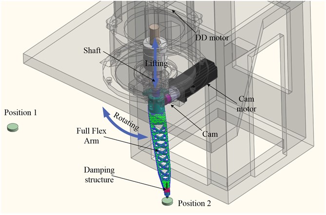
A virtual impact test is carried out before the physics experiment. The three arms are installed on a virtual test platform as Fig. 10 shown. The impact tests are carried out in the horizontal and vertical direction. The arm built by Full-Flex technology is fixed to the shaft, which, is driven by a DD motor and a cam rotating and lifting as in real working situations. The damping ratio is adopted from the damping experiment.
Fig. 10Virtual test platform
The impact signal in the drive motor shows in Fig. 11(a) and Fig. 11(b); the result of the simulation shows in Fig. 11(c) and Fig. 11(d), respectively. The vibration in Arm C eliminates in 10 ms at horizontal direction and 30 ms at vertical direction. Although Arm C gets the largest initial amplitude because of the particles on the front, the high damping ratio and dynamic stiffness promote it reaches the steady state the fastest of three arms.
Fig. 11Virtual impact test: a) horizontal impact, b) vertical impact, c) horizontal direction, d) vertical direction
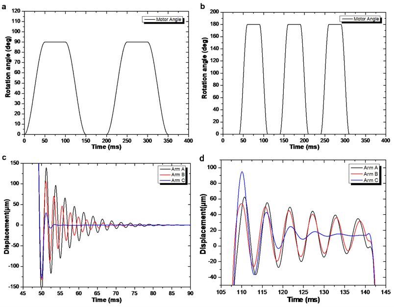
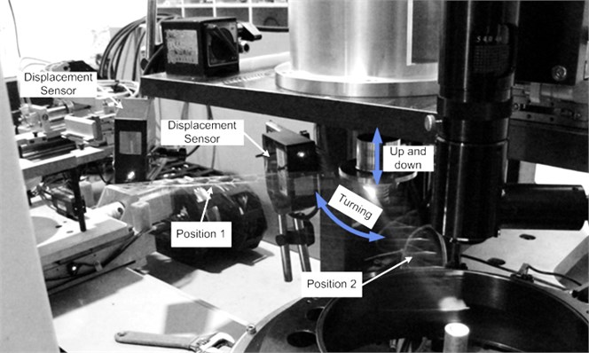
Fig. 12Test platform
4.3. Impact test
Finally, impact test was carried out to prove the validity of our method. The test platform setup as Fig. 12, the arm was installed at the end of the shaft driven by the DD motor. Two laser displacement sensors mounted at the limit position and get the displacement signal of the arm.
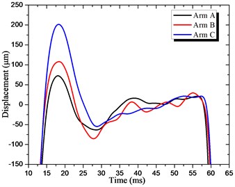
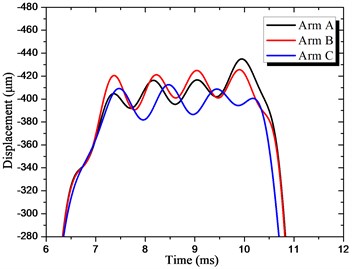
The measured displacements at the front of the arms were compared in Fig. 13. We can find that the Arm C has the largest amplitude at the beginning of impact, but the vibration was quickly attenuated because of the high damping ratio; Arm B has the smallest displacement for the largest dynamic stiffness, but the vibration continues for a longer time compared to Arm C; the Arm A can’t beat the vibration attenuation comparison with Arm C, neither the displacement comparison with Arm B. The results confirmed the validity of our approach.
Fig. 13Displacements at the end of arm: a) vertical direction displacement, b) horizontal direction displacement
a)
b)
5. Conclusions
This paper presents a vibrostabilization optimization method for the sorting arm. The optimized particle damping structure and an improved level set optimization algorithm have been adopted to eliminate the vibration quickly.
Based on the design rules of particle damping from Chan and Marhadi, this paper carried out the damping capsules filling ratio and distribution experiment. The result shows that the filling-ratio of damping capsules affect the damping ratio varies at different distribution. The final particle damping structure has achieved 0.72 % damping ratio on the classic arm.
A new parameterization level set topology optimization was deduced to optimize the structure of the arm. The new algorithm unifies design variables of topology, shape and geometric constraints into the expansion coefficients of optimization model, transforms the complex multi-variable optimization problem into a relatively simple sizing optimization problem. With the improved optimization method, the topology and shape of the arm are optimized in one time.
The impact experiment has been carried out, and the results confirm that our method can improve the vibration resistant design.
References
-
H. V. Panossian. Nonobstructive particle damping (NOPD) performance under compaction forces. Machinery Dynamics and Element Vibrations, Vol. 36, Issue 1, 1991, p. 17-20.
-
R. D. Friend, V. K. Kinra. Smart Structures and Materials 1999. International Society for Optics and Photonics, Newport Beach CA, 1999, p. 20-31.
-
R. D. Friend, V. K. Kinra. Particle impact damping. Journal of Sound and Vibration, Vol. 233, Issue 1, 2000, p. 93-118.
-
R. D. Friend, V. K. Kinra. Symposium on Smart Structures and Materials. International Society for Optics and Photonics, 1999, p. 20-31.
-
K. Mao, M. Y. Wang, Z. Xu, T. Chen. DEM simulation of particle damping. Powder Technology, Vol. 142, Issue 2, 2004, p. 154-165.
-
K. S. Marhadi, V. K. Kinra. Particle impact damping: effect of mass ratio, material, and shape. Journal of Sound and Vibration, Vol. 283, Issue 1, 2005, p. 433-448.
-
K. W. Chan, W. H. Liao, M. Y. Wang, P. K. Choy. Experimental studies for particle damping on a bond arm. Journal of Vibration and Control, Vol. 12, Issue 3, 2006, p. 297-312.
-
M. P. Bendsoe, O. Sigmund. Topology Optimization: Theory, Methods and Applications. Springer, 2004.
-
Z. Luo, J. Yang, L. Chen. A new procedure for aerodynamic missile designs using topological optimization approach of continuum structures. Aerospace Science and Technology, Vol. 10, Issue 5, 2006, p. 364-373.
-
J. A. Sethian, A. Wiegmann. Structural boundary design via level set and immersed interface methods. Journal of Computational Physics, Vol. 163, Issue 2, 2000, p. 489-528.
-
S. Osher, J. A. Sethian. Fronts propagating with curvature-dependent speed: algorithms based on Hamilton-Jacobi formulations. Journal of Computational Physics, Vol. 79, Issue 1, 1988, p. 12-49.
-
M. Y. Wang, X. Wang, D. Guo. A level set method for structural topology optimization. Computer Methods in Applied Mechanics and Engineering, Vol. 192, Issue 1, 2003, p. 227-246.
-
M. Y. Wang, X. Wang. PDE-driven level sets, shape sensitivity and curvature flow for structural topology optimization. CMES: Computer Modeling in Engineering & Sciences, Vol. 6, Issue 4, 2004, p. 373-396.
-
G. Allaire, F. De Gournay, F. Jouve, A. M. Toader. Structural optimization using topological and shape sensitivity via a level set method. Control and Cybernetics, Vol. 34, Issue 1, 2005, p. 59-80.
About this article
The research work sponsored in part by the Natural Science Foundation of China (Grant: 50975107), the Guangdong Province High-Tech Zone Development Guiding Program (Grant: 2011B010700081), the National Key Technologies R & D Program of China (Grant: 2010ZX04001-032), and also by the Dongguan City Small and Medium-Sized Enterprises Innovation Foundation (Grant: 201120 110107).
