Abstract
Structural and mechanical systems are assembled from smaller components using mechanical joints. The mechanical properties of the joints must be modeled in order to perform subsequent design and analysis of the structure or mechanical system. This study provides an analytical method of determining the parameters that describe the behavior of the joints using frequency response function (FRF) data that is measured at joint nodes. The variation in FRFs is derived by utilizing the consistent response conditions at the same joint nodes of the assembly system and the portioned subsystems. The variation reflects the mechanical properties of the joint and is utilized to extract the joint parameters. The validity of the proposed method is illustrated in two numerical applications.
1. Introduction
A significant amount of research has been done to understand how damage to a structural member affects the structural performance. Damage to a member leads to the reduction of structural stiffness and the local change in the static or dynamic response. Existing methods of damaging members do not provide an accurate means of determining the support conditions and the characteristics of the interior joints. The determination of the parameters that are used to describe the behavior of structural joints and how they provide support is important for developing a reliable method for detecting damage.
A complete system is composed of several subsystems that are interconnected by joints. It is described by the constrained system to synthesize the adjacent subsystems using compatibility conditions. Adversely, the constrained whole system is dissolved by removing the compatibility conditions between the adjacent subsystems. The mechanical properties of joints, such as the degree of damping provided and stiffness, affect the dynamic characteristic of the assembled system. This suggests that an erroneous evaluation or description of joint properties results in the inaccurate design and analysis. The joints have complicated properties that cannot be explicitly identified. Precise understanding of how joints behave under various conditions is required in order to accurately describe the dynamic response of a structure. The joint parameters affect the dynamic characteristics of an entire system and obtaining them accurately is difficult due to limited access and the inability to obtain accurate measurements.
FRF response data provide more information than modal data because the latter are obtained from a very limited frequency range that is related to resonance. A single FRF measured at several frequencies, along with a correlated analytical model of the structure in its original state, can be used for updating structural parameters.
Chae et al. [1] presented a method of characterizing joints using the response in the translational and rotational variables using experimental and finite element analyses. Zhang and Guo [2] updated techniques of obtaining joint parameters using a meta-model which utilizes a response surface method. Hwang [3] developed a method of determining joint parameters for real structures using FRF data. Wang et al. [4] derived the joint stiffness matrix based on joint deformation modes and discussed a structural joint model that facilitated a means for identifying joint damage. Wang et al. [5] developed a joint description method using partially measured FRF data that provides a means of determining the dynamic properties of joints within an assembled structure that consists of substructures. They also presented a method for estimating unmeasured FRFs.
Tol and Özgüven [6] described a method of using the FRFs of the substructures that are obtained either analytically or experimentally to describe the stiffness and damping values of joints. Celic and Boltezar [7] proposed a combined numerical and experimental approach to identify the mass, stiffness and damping effects of a bolted joint using the least-squares method. Ahmadian and Jalali [8] identified the parameters of the joint by minimizing the difference between the model predictions and the experimentally measured data with normal and tangential stresses at the joint interface. Wang and Chuang [9] identified the structural joint parameters directly from the FRFs of the substructures and the whole structure. Yang et al. [10] considered an identification method by using the substructure synthesis method and FRFs at only two measurement points. Ren and Beards [11] proposed techniques for improving the accuracy of joint identification from the measured FRF data. Chen et al. [12] proposed a finite element identification method based on finite element simulation and the curve fitting principles, fitting out a curve that closed to simulation results. Ingole and Chatterjee [13] modeled structural joints and developed frequency equation of the overall system using sub-structure synthesis, and applied multi-linear regression method to estimate the unknown stiffness matrices. Jalali et al. [14] identified the parameters of an assumed nonlinear joint model by force-state mapping from time-domain acceleration records in response to single-frequency excitation close to the first natural frequency.
Structural and mechanical systems are assembled by connecting the individual members using joints. The mechanical properties of the real joints cannot be explicitly described and their inaccuracy leads to the incorrect analysis and design. This work presents a method of determining the joint parameters using measured FRF data only. The variation in FRFs that depend on the location of a joint is determined by utilizing the consistent response conditions at the joint nodes of an assembled system and the partitioned subsystems partitioned subsystems that provide a means of removing the joint. The variations characterize the mechanical properties of the joint and the joint parameters are extracted from them. The validity of the proposed method is illustrated using two numerical methods.
2. FRF-based joint identification
The dynamic behavior of a system that is assumed to be linear and approximately discretized for DOFs can be described by the equations of motion in the time domain as:
where , , and denote the analytical mass, damping, and stiffness matrices, denotes the displacement vector and is the excitation vector.
A relationship between FRF and modal parameters should be established for successful modal testing. Inserting and into Eqn. (1) and expressing it in the frequency domain, it follows that:
where denotes the excitation frequency, is an external force vector with an element being unit and all other elements zeros in the frequency domain and . And is the displacement response amplitude vector in the frequency domain. Using the FRF matrix, the response of the structure, described by , to an external excitation, described by , is given by:
where is the FRF matrix of the structure, the elements of which represent the receptances.
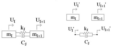
Fig. 1Identification of joint parameters: a) an entire system, b) two subsystems and a joint, c) dissolved joint-node systems and a joint

a)

b)
c)
The determination of joint parameters is begins with experimentally measuring FRF data. The FRF response data are obtained by the roving of accelerometer under the excitation of the impact hammer at a reference point or by an accelerometer measurement at a reference with the roving of the hammer. FRF response data are obtained by taking accelerometer measurements in a single location and varying the placement of an impact hammer, or by specifying the location of the hammer and varying the placement at which accelerometer measurements are made. The measured FRF response in Eqn. (3) indicates a displacement response at station and a disturbing force at station . The joint parameters are determined by analyzing only the FRFs that are measured.
The assembled system shown in Fig. 1(a) is composed of two subsystems and a joint of damping and stiffness between the nodes and in Fig. 1(b). This identification method is processed by removing the joint effect from the entire system. The response at the joint nodes of the assembled system in Fig. 1(a) doesn’t coincide with the corresponding response of the partitioned subsystems of Fig. 1(b) because the joint is removed. The inconsistency is utilized as the fundamental means of determining the joint parameters. The response at joint nodes of the partitioned subsystems can be obtained by removing the forces at the joint nodes from the assembled system.
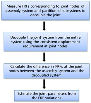
The forces indicate the forces required for satisfying the constant displacement at the given joint nodes of an assembled system and decoupled subsystem. The mechanical properties of the joint can be identified by the accurate estimation of the forces. The identification method of joint parameters proposed in this study is summarized in Fig. 2.
The dynamic equations that relate the input and the output of an assembled system and the subsystems are written as follows:
where the subscripts and represent the inner and joint nodes, and denotes the FRF matrix of the decoupled subsystems. The apostrophes denote the subsystem. And the displacement response vectors are defined as:
Fig. 2Identification of joint parameters
It is not necessary to collect the FRF data corresponding to the full set of DOFs of the assembled system. The analysis is performed using only the FRF data at the joint nodes rather than the full set of DOFs as shown in Fig. 1(c). From the second equations of Eqns. (4a) and (4b), the dynamic equations of both systems at the joint nodes can be written as:
The displacement constraints represent the same response at the joint nodes of both systems in Fig. 1(c) can be written as:
Based on the generalized inverse method [15], the dynamic responses at the joint nodes of the entire system and the decoupled subsystems can be written as:
where denotes the consistent displacements at the joint nodes of both systems, , , , denotes the Moore-Penrose inverse and the matrix is the Boolean matrix used to define the joint nodes. The constant displacement vector is obtained by releasing the displacement vector from the entire response or by adding the displacement from the decoupled subsystems. Therefore, Eqn. (7) based on the generalized inverse method can be rewritten as:
where is the measured FRF matrix at the joint nodes. The coefficient matrix in Eqn. (8) describes the FRF matrix of the residual system that is used to remove a joint from the analysis. Premultuplying both sides of Eqn. (8) by , the second term of the right hand side of the result describes the constraint forces for the decoupled or assembled system:
The coefficient matrix of the force vector represents the FRF matrix that is used to decouple the joint element. The FRF difference corresponding to the joint of the decoupled system and the assembly system provides a means of obtaining the joint FRFs.
The difference in the experimentally collected FRF data matrix between both systems can be written as:
where , and denote the real and imaginary parts of the FRF matrix. Considering the variation in the parameter matrices under the assumption of the invariant mass matrix , Eqn. (10) can be modified as:
Arranging Eqn. (11) into real and imaginary parts results in:
Solving the simultaneous equations shown in Eqn. (12) with respect to and within a specific frequency range gives:
The variations in the parameter matrices given by Eqns. (13) denote the dynamic properties of only the joint. The parameters of the joint, and take the eigenvalues of the matrices and , respectively that correspond to the vibration mode due to the effect of the constraint forces as shown in Fig. 1.
3. Example
As an example, we will determine the support joint stiffness and damping parameters as outlined in Fig. 3. The entire system consists of five DOFs. The measured FRFs are replaced by the numerically simulated values that are modified by adding 3 % noise. In the decoupling process of the joint, we consider two subsystem cases of two DOF systems by the joint nodes and 10 DOF system including the inner nodes of . Both cases have a constraint of the constant response at the joint node as:
The following values were used for this numerical example where:
Fig. 3An entire system and the decoupled systems: a) an entire system of five DOFs, b) subsystems partitioned into a support and a remaining substructure

a)

b)
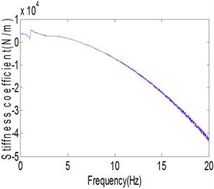
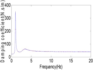
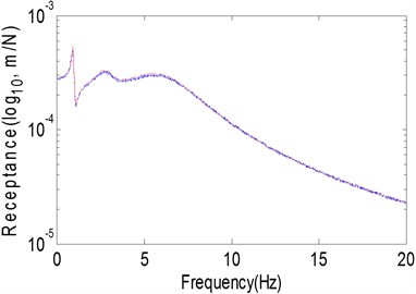
Figure 4 compares the estimated stiffness and damping coefficients of both cases. It is shown that both plots are identical with the exception due to the added 3 % noise. This indicates that the joint parameters can be determined by evaluating the dynamic equation that corresponds to the joint nodes only. Subsequent analysis is performed by using a numerical experiment with the second subsystem by analyzing only two joint nodes of two DOFs. Figure 5(a) displays the receptance magnitude of the entire system in the range of 0.01-20 Hz using increments of 0.02 Hz. It is observed that 0.91 Hz is the first resonant frequency.
Fig. 4Estimated parameters: a) stiffness, b) damping
a)
b)
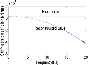
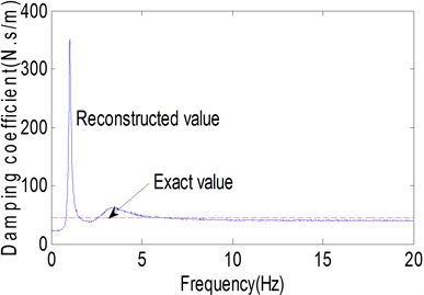
Figures 5(b) and (c) plot the estimated stiffness and damping coefficients at each frequency which are obtained using Eqns. (13). The plots of the stiffness and damping coefficients have constant values within different ranges of frequency. The stiffness takes a constant value in the neighborhood of the first resonance frequency and the damping data in the range of 6-10 Hz. Utilizing Eqns. (13) and POM (proper orthogonal mode) approach, the stiffness and damping values were calculated as 3508.8 N/m and 42.47 N⋅s/m in the frequency range of 0.3-0.4 Hz and 7-8 Hz, respectively. The estimated stiffness and damping values have the errors of 2.62 % and 5.62 %, respectively. It is determined that the proposed method properly estimates the joint parameters. The receptance magnitude was reconstructed using the estimated values. The reconstructed receptance magnitude was plotted in Fig. 5(a) and it was almost the same except for the variation that is due to the effects of added noise.
Fig. 5Parameter identification of end support: a) receptance magnitude, b) stiffness, c) damping
a)
b)
c)
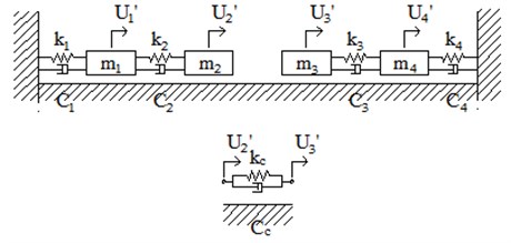
Fig. 6An entire system and subsystems: a) an entire system of four DOFs, b) subsystems partitioned into two subsystems and a joint

a)
b)
In a second example, we considered a dynamic system shown in Fig. 6. The assembled system consists of two substructure systems with a joint between two nodes 2 and 3 as shown in Fig. 6(b). The joint has stiffness and damping coefficients of and , respectively. The FRF variation between two systems describes the mechanical properties of the joint by matching the dynamic response at the nodes of the entire structure and the substructures. Extracting the FRFs corresponding to the joint nodes from both systems is given by:
where FRFs are assumed as measured data.
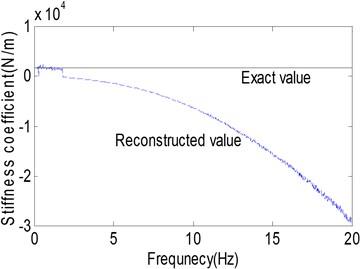
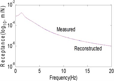
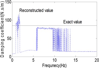
Fig. 7Identification of joint parameter: a) receptance magnitude, b) stiffness coefficient, c) damping coefficient
a)
b)
c)
The numerical values of the assembled system for this application were selected as follows:
Figure 7(a) represents the receptance magnitude of that indicates a displacement response at station 1 and a disturbing force at station 2.
The numerically simulated curve is obtained by adding 3 % external noise as a substitute of measured data. The first resonance frequency is located at 1.21 Hz. Figures 7(b) and (c) show the stiffness and damping coefficients at each frequency in the range of 0.01-20 Hz in steps of 0.02 Hz. It can be seen that the stiffness gradually decreases with increasing frequency in a way that it cannot be predicted. The stiffness can be determined as the value that corresponds to the first resonance frequency. The damping can be identified by using the constant value in the frequency range of 6-10 Hz which is larger than the first resonance frequency used to obtain the stiffness. Utilizing Eqns. (13), the stiffness and damping were estimated as 1651.3 N/m and 75.94 N⋅s/m in the frequency range of 1-1.6 Hz and 7-8 Hz, respectively. The estimated stiffness and damping values have errors of 2.86 % and 10.65 %, respectively. It is understood that the errors come partially from the external noise. Figure 7(a) represents the reconstructed FRF receptance magnitude using the estimated parameter values. It can be seen that both plots are almost the same. From these applications, it can be concluded that the proposed method can produce some discrepancy as compared to the actual parameter values which indicates the analysis technique needs further refinement.
4. Conclusions
This study provided an analytical method that may be used to identify the joint parameters for all nodes using measured FRFs. It method does not require FRF information of the inner nodes. The variation of the FRF was derived using the constant response condition at the joint nodes of the entire system and the partitioned substructures, and the joint parameters were identified from the FRF variations. The validity of the proposed method was illustrated in two examples and it was shown that the proposed method properly identifies the joint parameters. However, this method requires further refinement for obtaining the most accurate results.
References
-
Chae J., Park S. S., Lin S. Substructure Coupling with Joint Identification for Reconfigurable Manufacturing Systems. library.queensu.ca/ojs/index.php/PCEEA/article/download/3956/3913.
-
Zhang L., Guo Q. Identification of the mechanical joint parameters with model uncertainty. http://sem-proceedings.com/24i/sem.org-IMAC-XXIV-Conf-s27p07-Identification-Mechanical-Joint-Parameters-with-Model-Uncertainty.pdf.
-
Hwang H. Y. Identification techniques of structure connection parameters using frequency response functions. Journal of Sound and Vibration, Vol. 213, 1998, p. 469-479.
-
Wang D., Friswell M. I., Nikravesh P. E., Kuo E. Y. Damage Identification in Structural Joints Using Generic Joint Elements. http://michael.friswell.com/PDF_Files/C96.pdf.
-
Wang M., Wang D., Zheng G. Joint dynamic properties identification with partially measured frequency response function. Mechanical Systems and Signal Processing, Vol. 27, 2012, p. 499-512.
-
Tol Ş., Özgüven H. N. Dynamic characterization of structural joints using FRF decoupling. Proceedings of the SEM IMAC XXX Conference, Vol. 5, 2012, p. 449-460.
-
Celic D., Boltezar M. Identification of the dynamic properties of joints using frequency-response functions. Journal of Sound and Vibration, Vol. 317, 2008, p. 158-174.
-
Ahmadian H., Jalali H. Identification of bolted lap joints parameters in assembled structures. Mechanical Systems and Signal Processing, Vol. 21, 2007, p. 1041-1050.
-
Wang J. H., Chuang S. C. Reducing errors in the identification of structural joint parameters using error functions. Journal of Sound and Vibration, Vol. 273, 2004, p. 295-316.
-
Yang T., Fan S.-H., Lin C.-S. Joint stiffness identification using FRF measurements. Computers & Structures, Vol. 81, 2003, p. 2549-2556.
-
Ren Y., Beards C. F. Identification of joint properties of a structure using FRF data. Journal of Sound and Vibration, Vol. 186, 1995, p. 567-587.
-
Liu X., Zhang K., Li M. An identification method for joint parameters based on finite element. Advanced Materials Research, Vol. 690-693, 2013, p. 2866-2871.
-
Ingole S. B., Chatterjee A. Joint parameter identification of a cantilever beam using sub-structure synthesis and multi-linear regression. Structural Engineering & Mechanics, Vol. 45, 2013, p. 423-437.
-
Jalali H., Ahmadian H., Mottershead J. E. Identification of nonlinear bolted lap-joint parameters by force-state mapping. International Journal of Solids and Structures, Vol. 44, p. 8087-8105.
-
Rahmatalla S., Eun H. C., Lee E. T. Damage detection from the variation of parameter matrices estimated by incomplete FRF data. Smart Structures and Systems, Vol. 9, 2012, p. 55-70.
About this article
This work was supported by the National Research Foundation of Korea (NRF) Grant funded by the Korea Government (MEST) (No. 2011-0012164).
