Abstract
Two piezoelectric bending actuators of a novel design are presented and analysed in the paper. Numerical modelling and experimental study of the piezoelectric bending actuators were performed to verify operating principle and to investigate dynamic characteristics of the actuators. Numerical calculations are performed by using finite element method. Results of experimental study of piezoelectric actuators are compared with the results of finite element simulations. Results of the numerical and experimental research are analysed and discussed.
1. Introduction
Piezoelectric cantilever bending actuators are widely used in many micromanipulation and microrobotic applications due to high resolution and fast response time [1]. Classical examples of piezoelectric cantilever bending actuators have unimorph, bimorph and multimorph configurations. Such actuators with a simple design are capable of producing large stroke under low electric voltage and provide high mechanical force/load sensitivity as sensory devices [2].
A bimorph bender consists of two piezoelectric thin plates with polarization perpendicular to the interface plane (Fig. 1(a)). One plate is expanding while another is contracting when electric field is applied on the electrodes of the actuator. Since there is constraint at the interface of these two plates, bending deformation occurs in the whole structure. Similarly, bending can be produced in the unimorph actuator, where the transverse deformation of the piezoelectric plate is constrained by the passive elastic plate (Fig. 1(b)). Therefore, bimorph and unimorph structures can be used as actuation elements. Triple layer benders, which consist of two piezoelectric layers and a sandwiched central elastic layer (Fig. 1(c)) can be used to improve the mechanical reliability. However, in any case, the interfaces in the bimorph, unimorph or triple layer benders are mechanically weak locations. Delamination may occur after being driven for a period of time under periodic excitations due to the relaxation and debonding of the adhesive materials [1-3].
Fig. 1The schemes of piezoelectric bending actuators: a) piezoelectric bimorph, b) piezoelectric unimorph, c) piezoelectric triple layer bender [1-3]
![The schemes of piezoelectric bending actuators: a) piezoelectric bimorph, b) piezoelectric unimorph, c) piezoelectric triple layer bender [1-3]](https://static-01.extrica.com/articles/14595/14595-img1.jpg)
![The schemes of piezoelectric bending actuators: a) piezoelectric bimorph, b) piezoelectric unimorph, c) piezoelectric triple layer bender [1-3]](https://static-01.extrica.com/articles/14595/14595-img2.jpg)
Seeking to bond all layers of piezoelectric benders, adhesives are used. For instance, the adhesives used for bonding the piezoelectric patch have a finite service life, usually shorter than the host structure’s life-span [4, 5].
Two novel design piezoelectric bending actuators are presented in this paper. These actuators consist of one piezoelectric plate and electrodes with the special design. Comparing them to the classic piezoelectric bending actuators, they have no bonding layer between piezoelectric plates, so influence of the bonding layer is avoided. Modelling based on finite element method was performed to make modal and harmonic response analysis of the actuators. Experimental investigations were made to define the dynamic characteristics of the actuator.
2. Design of novel piezoelectric benders
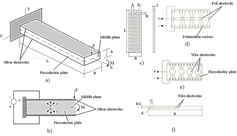
Investigated piezoelectric bending actuators consist of piezoelectric plate and electrodes (Fig. 2a). Silver electrodes are placed on top and bottom of actuator, and are used apply driving voltage (Fig. 2b). Two different types of platinum electrodes are placed in the middle plane of piezoelectric plate during the sintering process of ceramics and are used for polarizing of piezoelectric plate as it is showed in Fig. 2d and Fig. 2e. In one case perforated foil platinum electrode is used as middle electrode (Fig. 2c). In other construction wire electrodes are placed along the length of actuator, in middle plane of it, and they are positioned as it can be seen in Fig. 2f. Parameters of piezoelectric material and geometric parameters of actuators are given in Table 1 and Table 2.
Fig. 2Structure of novel design piezoelectric bending actuators: a) isometric view of novel design piezoelectric actuator, where L, B, h – geometric parameters of cantilever, F and M – bending force and moment; b) polarization of piezoelectric plate, where P – direction of polarization; c) shape of perforated foil electrode placed in middle plane, where L, A, D, E, t – geometric parameters of foil-type electrode; d) polarization scheme of piezoelectric bender with inner foil-type electrode; e) polarization scheme of piezoelectric bender with inner wire-type electrodes; f) cross section of piezoelectric bender with inner wire-type electrodes, where d and C – geometric parameters of wire-type electrode
3. Modelling of bimorph actuators
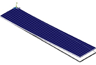
Finite element software ANSYS v.13 was used to perform numerical modelling of the two bimorph actuators – classic design and novel with wire-type electrodes. The aim of the modelling was to perform modal-frequency and harmonic response analysis of the actuators. Finite element model was made of SOLID5 and SOLID45 finite elements [6, 7]. It was assumed that polarization direction of the piezoceramic is constant within the finite element pale and is organized as shown Fig. 2e. The dimensions and material properties of the finite element models are given in Table 1 and Table 2. One end of the bimorph actuator was clamped so all mechanical degree of freedom of corresponding nodes was set to zero. The electrodes layers on the top and bottom of the actuator were not considered in the FEM model because their mechanical behaviour can be neglected due to their thickness. Electrodes were created by grouping surface nodes of the FEM model and harmonic voltage of excitation 145 V were applied.
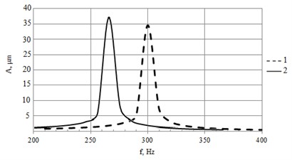
The modal shapes and the resonant frequencies of the actuators were calculated and harmonic response analysis was performed. The first bending mode out of plane is the object of interest and natural frequency of this mode was found at 275 Hz for classic actuator (two piezoelectric plates glued together) and at 300 Hz for the second actuator with wire-type electrodes (Fig. 2f).
Peaks in the graphs (Fig. 3) indicate the resonant vibrations at first bending mode. Resonance amplitudes are 37 µm and 35 µm accordingly for classic and second actuator with wire-type electrodes.
Table 1Parameters of piezoelectric material
Material | Pz 26 | |
Piezoelectric constants, (m/V×10-12) | -130 | |
360 | ||
Coupling factor, | 0,57 | |
Density , kg/cm3 | 7700 | |
Dielectric constant | 1300 | |
Mechanical constant | 1000 | |
Young’s modulus , GPa | 63 | |
Relative dielectric constant | 1000 | |
Table 2Geometric parameters of the piezoelectric benders
Length L, m | 0,045 |
Width B, m | 0,0042 |
Height h, m | 0,0017 |
Distance between wires C, m | 0,00035 |
Wire electrode diameter d, m | 0,0001 |
Distance between the holes in foil electrode A, m | 0,0003 |
Distance between the holes in foil electrode E, m | 0,0003 |
Diameter of holes in foil electrode D, m | 0,0004 |
Thickness of foil electrode t, m | 0,0001 |
Fig. 3Harmonic analysis: a) FEM model, b) amplitude-frequency response of piezoelectric actuator with wire electrodes (numerical simulation). Here 1 – novel design bender, 2 – classic piezoelectric bimorph
a)
b)
4. Experimental results
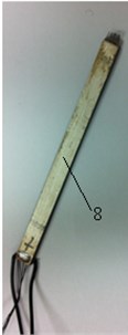
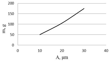
Prototype actuator with wire-type middle electrode (Fig. 2(f)) was made for experimental investigation (Fig. 4(b)). During experiments there were investigated two characteristics of bimorph actuators: rigidity of piezoelectric cantilever actuator with wire-type electrodes and amplitude-frequency response. The aims of experiment were to verify results of numerical modelling.
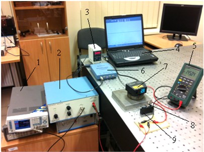
The experimental setup is shown in Fig. 4(a). It consists of: 1 – signal generator Agilent 33220A, 2 – power amplifier EPA-104, 3 – laser sensor controller LK-G3001PV, 4 – computer, 5 – multimeter MS8218, 6 – analog digital converter (ADC) “PicoScope-3424”, 7 – laser displacement sensor LK-G82, 8 – piezoelectric bending actuator, 9 – holder of piezoelectric bender.
Fig. 4Experimental investigation: a) setup and b) piezoelectric actuator used in experiments
a)
b)
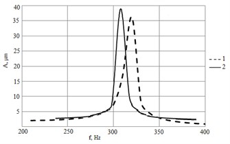
As a result of experiments we have amplitude-frequency responses that are shown in Fig. 5. Experimental results confirm the results of numerical modelling of piezoelectric bender with wire-type electrodes.
Fig. 5Experimental results: a) rigidity of piezoelectric cantilever actuator with wire-type electrodes and b) amplitude-frequency responses. Here 1 – novel design bender, 2 – classic piezoelectric bimorph
a)
b)
The experimental results have confirmed harmonic analysis of piezoelectric actuator wire-type electrodes. Comparing amplitude-frequency responses of novel bender and classic bimorph it can be seen, that resonance frequency increases from 305 Hz till 312 Hz, for novel design benders, but amplitude decreases by 7 % (Fig. 5(b)).
Novel design piezoelectric benders have very wide area of applications, such as sensor systems, printing technologies, positioning transducers, viscosity measurement systems, flow measurement systems, energy harvesting, laser beam controlling systems, pneumatic valves for industrial and automotive applications, valves in medical applications, insulin pumps, braille keys for the blind, textile machinery, optical switches, oil exploration, machine and equipment monitoring, automotive engines, feedback sensors, high temperature accelerometers, gyroscope sensors, intrusion alarms and many other devices. So development and investigations of such types of piezoelectric actuators are very important.
5. Conclusions
Novel design piezoelectric benders have very wide area of applications. Comparing amplitude-frequency responses of novel bender and classic bimorph it can be seen, that resonance frequency increases from 305 till 312 Hz, for novel design benders, but amplitude decreases by 7 %. Comparing them to classic piezoelectric bending actuators, they have no bonding layer between piezoelectric plates, so absence of bonding layer improves the performance and reliability of the actuator. Comparing numerical and experimental results it can be seen small difference between them (numerical values are different for classic actuator for 9 % and for novel –4 %). These differences can be explained in many different factors during theoretical investigation and real experiments, such as: material properties, bounding conditions, damping, temperature of environment and other.
References
-
Ivan I. A., Rakotondrabe M., Lutz P., Chaillet N. Quasistatic displacement self-sensing method for cantilevered piezoelectric actuators. Review of Scientific Instruments (RSI), Vol. 80, Issue 6, June 2009, p. 065102.
-
Wang Q., Du X., Xu B., Cross L. E. Theoretical analysis of the sensor effect of cantilever piezoelectric benders. Journal of Applied Physics, Vol. 85, No. 3, February 1999.
-
Zhu D., Almusallam A., Beeby S. P., Tudor J., Harris N. R. A bimorph multi-layer piezoelectric vibration energy harvester. PowerMEMS 2010, Leuven, Belgium, December 2010.
-
Park S., Park G., Yun Ch., Farrar Ch. F. Sensor self-diagnosis using a modified impedance model for active sensing-based structural health monitoring. Structural Health Monitoring, January 2009, p. 71-82.
-
Yamada K., Matsuhisa H., Utsuno H. A new method for accurately determining the modal equivalent stiffness ratio of bonded piezoelectric structures. Journal of Sound and Vibration, Vol. 331, No. 14, 2012, p. 3317-3344.
-
Yoo J. H., Hong J. I., Cao W. Piezoelectric ceramic bimorph coupled to thin film metal plate as cooling fan for electronic devices. Sens. Actuators A, Vol. 79, 2000, p. 8-12.
-
Sitti M., Campolo D., Yan J., Fearing R. Development of PZT and PZN-PT Based Unimorph Actuators for Micromechanical Flapping Mechanisms. Constant Magnet Motors, USA, 2001.
-
Tzou H. S. Piezoelectric Shells (Distributed Sensing and Control of Continua). Kluwer Academic Publishers, 1993, p. 320.
-
Han J. M., Adriaens T. A., Koning W. L., Banning R. Modelling Piezoelectric Actuators. IEEE/ASME Transactions on Mechatronics, Vol. 5, No. 4, December 2000, p. 331.
-
Muralt P., Pohl D. W., Denk W. Wide-range, low-operating-voltage, bimorph STM: applications as potentiometer. IBM J. Res. Develop., Vol. 30(5), 1986, p. 443-450.
-
Parashar S., Das Gupta A., Von Wagner U., Hagedorn P. Non-linear shear vibrations of piezoceramic actuators. International Journal of Non-Linear Mechanics, Vol. 40, 2005, p. 429-443.
About this article
This research is funded by the European Social Fund under Project “Microsensors, Microactuators and Controllers for Mechatronic Systems (Go-Smart)” (Agreement No. VP1-3.1-ŠMM-08-K-01-015).
