Abstract
The paper presents investigations of gas tungsten arc welding process with the aim of enhancing the quality of welded joints. Specific attention was given to arc voltage, welding current, wire feed rate values during the welding. In order to monitor and to investigate the gas tungsten arc welding process piezoelectrical sensors have been used during experimental tests. The comments about formation of weld pool and heat affected zone as a result of welding parameters also are presented.
1. Introduction
Gas tungsten arc welding (GTAW), also known as tungsten inert gas (TIG) welding is a process that produces an electric arc maintained between a non-consumable tungsten electrode and the part to be welded. The arc area is surrounded by an inert or reducing gas shield to protect the weld pool (the melted region of the workpiece) and the non-consumable electrode. This gas shielding process prevents any oxidation of the weld and allows for the production of neat, clear welds. The TIG process is capable of producing very high quality welds in a wide range of metals – mild steel, low alloys, stainless steels, aluminium and aluminium alloys, copper and copper alloys, nickel and nickel alloys, magnesium and magnesium alloys, titanium and others. This method is most extensively used for welding primarily steel and aluminium. Steel is relatively easy to GTAW weld and it is possible to have very tight, neat welds. Aluminium welding requires a little more skill and it is necessary to have a little bit of experience in welding steel before making the transition to aluminium. GMAW probably the most successful and widely used welding method in industry today, so the quality of a weld is a key issue in welding process. TIG welding is a highly non-linear, strongly coupled, multivariable process [1]. The weld pool geometry and, hence, the quality of welded joints are greatly dependent on the selection of input control variables such as shielding gas flow rate, welding travel speed, welding current, wire feed rate value, arc voltage, etc.
It is well known that thermal and force parameters of a welding process depend to a large extent on torch velocity, arc voltage and welding current [2, 3, 4, 5]. The weld width and the depression (the ratio of S and l, where S weld pool area and l weld width) are very important by the thermal and force parameters. Thus, weld width and depression can be changed by adjusting the velocity, arc length and welding current. The major effect of a change of velocity is in the power density of the heat source. Therefore, the latter can be fully controlled by welding current and arc voltage or arc length. Thus, it should be noticed that the welding current and arc voltage generally are chosen to be the control variables. The relationship between welding current and arc voltage is not a straight line. Also, metal transfer control, which refers to the task of providing detachment of liquid metal drops from the tip of the welding electrode, is an important parameter to the overall quality of the weld [6]. Control of the total TIG process can be separated into weld pool control and drop and arc control.
The structure and chemical composition of the base metal differs from the metal of the weld. The dimensions, structure and chemical composition of the weld and heat affected zone (HAZ) have significant influence on the quality of the welded joint. HAZ is that part of the base metal which not melts, but, under the influence of the heat, both the structure and properties of HAZ are changing during the welding process and plastic deformations appear. High heat input results in considerable variation in microstructure of weld metal and HAZ. The heat input used in the welding should be restricted to lower range. Weld thermal cycle associated with chemical compositions of welding wires is known to directly affect both the macro and microstructure of weld metal and the HAZ which in turn has an influence on the mechanical properties of the welding joint [6, 7]. Relatively small dimension HAZ can cause the formation of slots, whereas relatively large dimension HAZ can result significant deformations. Moreover, the mechanical properties of HAZ, except the normalization region, are worse if compared to that of a base metal. The dimensions of this region depend on welding method, welding regimes and chemical composition of the base metal. Thus, it is very important to control HAZ formation process and predetermine the structure and dimensions of HAZ.
2. Experimental setup and conditions
The experimental setup is shown in Fig. 1. Choice of equipment depends upon the type of metal being joined, the position of the weld being made and the quality of the weld metal necessary for the application.
Fig. 1Block diagram of the experimental setup: 1 - welding machine, 2 - LF charge amplifier, 3 - tunable band pass filter, 4 - oscilloscope, 5 - piezoelectric sensor, 6 - signals’ acquisition and processing device, 7 - multichannel signal modulator, 8 - converter, 9 - microprocessor, 10 - display
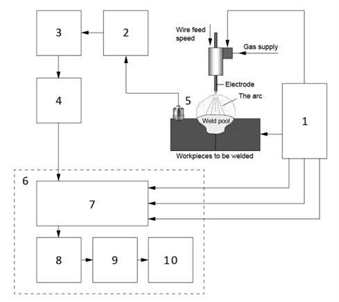
Three type workpieces made of carbon steel and having different thickness (4 to 15 millimeters) were used: solid metal, i.e. welding was done directly on workpiece‘s surface, welding of two separate workpieces, and welding on a groove. Gas tungsten arc welding method, in the Ar/CO2 protective gas environment, by using the fusible electrode from tungsten was analyzed. The welding with fusible electrode requires relatively large density welding current, therefore, small diameter (0.8 mm) welding wire, which was fed into electric arc by a relatively high feed rate, was used. Welding experiments were carried out under different values of welding current and arc voltage (see Table 1).
In order to obtain the stable welding process, it is necessary to control the duration of the liquid drop formation, passing the arc length and dropping to the weld pool, as well as the dimensions of the formed drop and speed variation of the electrical parameters. To control the process, of the electrode metal transfer into the melted metal pool, which has the direct impact on the weld quality, the precise registration of the mentioned above parameters is an essential condition.
Table 1Welding regimes parameters
No. of welding regime | Welding current, A | Arc voltage, V | No. of welding regime | Welding current, A | Arc voltage, V |
1 – 1 | 35.1 | 14.7 | 6 – 6 | 153.9 | 24.2 |
2 – 2 | 68.4 | 15.2 | 7 – 7 | 169.0 | 25.4 |
3 – 3 | 84.9 | 20.5 | 8 – 8 | 193.5 | 26.8 |
4 – 4 | 95.4 | 21.2 | 9 – 9 | 218.6 | 27.1 |
5 – 5 | 105.8 | 21.8 | 10 – 10 | 249.8 | 27.5 |
During the experiments the accelerometer (Brüel&Kjǽr 4367) was used to monitor and control the metal transfer process. Piezoelectrical sensor was made of Pz 23 (lead zirconate titanate-soft) and the body – from titanium. Pz 23 material is characterized by relatively high Curie temperatures (> 350°C), low mechanical quality factor, high electrical resistivity and sensitivity (2 mV/ms-2 or pC/ms-2) at elevated temperatures (Ferroperm Piezoceramics A/S). Thus, the piezoelectrical sensor may be placed close to the welding pool (≈ 50 cm).
For the welding process analysis the software and special signal data acquisition and processing device (4 inputs: arc voltage, welding current, wire feed speed and piezoelectrical sensor signal) were developed (Fig. 1).
The signals’ data acquisition device comprises four amplifiers for the signals being observed during the welding process, as well as the corresponding sensors for wire feed rate, welding current strength, arc voltage and piezoelectric sensor signals measurement. The input ranges of the used piezoelectric sensor: 0 to 1 V, 0 to 10 V and 0 to 100 V.
3. Experimental results and discussions
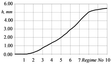
The experimental results showed that composition of the metal and electrode, as well as conditions of the electrode metal transfer into the weld pool, the corresponding electrical parameters (welding current and arc voltage) and feed rate of the wire have the significant influence on the weld quality and HAZ formation process. HAZ depth dependence of welding parameters is shown in Fig. 2. The geometry of HAZ mainly depends on metal transfer regime, which can be of two types: short circuit transfer and drop metal transfer. During the short circuit transfer, melted metal passes into the weld pool due to a direct contact of the electrode and base metal. The relatively high current (more than 170 A) results the drop transfer of the melted metal. The size of the drop depends on the power of arc current. By increasing the power of arc current it is possible to ensure almost stream flow transfer of the electrode metal into the weld pool.
Fig. 2HAZ depth dependence on electrical parameters of welding
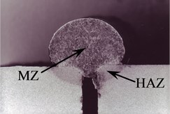
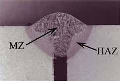
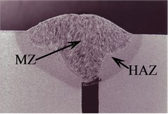
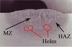
The dimensions of the metal drops have an influence on the metallurgical processes and overheat of the weld pool. The weld pool overheat is more rapid under relatively large droplet of the melted metal. Fig. 3 shows cross-sections of the welds under different regimes of welding. The weld presented in Fig. 3a was obtained under welding current 84.9 A, arc voltage 20.5 V and 4.03 mm/s wire feed rate, whereas the weld in Fig. 3f under 193.5 A, 26.8 V and 9.23 mm/s respectively.
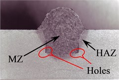
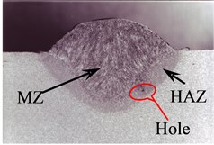
Fig. 3Optical cross-section micrographs of welds: a), b), c) welding regimes 3-3, 6-6 and 8-8 respectively of two separate weldments; d), e), f) welding regimes 3-3, 6-6 and 8-8 respectively of welding on grooves
a)
b)
c)
d)
e)
f)
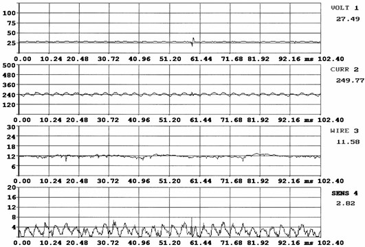
Basic electrical parameters of welding, the wire feed rate and the time, of metal drop falling to the weld pool, which was registered by the piezoelectrical sensor, are shown as waveforms of the signals (Figs. 4-6). Due to the stream flow transfer of the electrode metal into the weld pool (small metal droplets continuous detaching from the electrode), the changes in electrical parameters (recorded oscillograms) show only the slight variation of the electrical parameters (Fig. 6).
Fig. 4Waveforms of arc voltage, welding current, welding wire feed rate and piezoelectric sensor’s signal (welding regime 3-3)
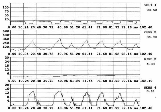
Metal drops’ transfer regime may be analyzed by the spectral analysis of the piezoeletrical sensor as well. The method of the electrode metal transfer has a significant impact on the shape and quality of the weld. In Figs. 4-6 it could be easily observed differences in welds under different weld regimes. The weld example (Fig. 5) was obtained under 153.9 A welding current, 24.2 V arc voltage, 6.46 mm/s wire feed rate, 4.40 mm/s welding travel speed (welding regime 6-6), whereas the weld in Fig. 4 was obtained under 84.9 A weld current, 20.5 V arc voltage, 4.03 mm/s wire feed rate and 4.40 mm/s welding travel speed (welding regime 3-3).
Fig. 5Waveforms of arc voltage, welding current, welding wire feed rate and piezoelectric sensor’s signal (welding regime 6-6)
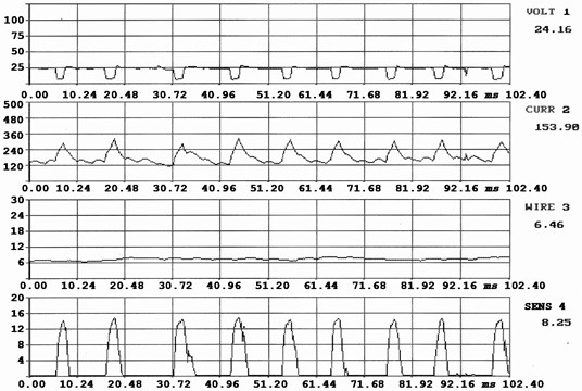
Fig. 6Waveforms of arc voltage, welding current, welding wire feed rate and piezoelectric sensor’s signal (welding regime 10-10)
To analyse the mechanical parameters both of the weld and HAZ, the hardness measurements by Vickers method were accomplished. The experiments showed that the maximum hardness values are in the weld zone, whereas HAZ has the worse strength properties. In order to have the weld joint of required mechanical properties, it is recommended to reduce the dimensions of HAZ.
The welding experiments showed that increase in welding current causes the increase in HAZ, whereas the higher welding travel speed reduces HAZ area. During the welding experiments, the welding travel speed was varied from 0.98 mm/s up to 6.14 mm/s.
Good quality welding depends on two major factors – the penetration of the weld into the base metal and the melt-off rate of the electrode. At all grindings (Fig. 3) one can easily see the boundaries of the melted zone (MZ), and the HAZ. The single crystals are here easy to recognize and they are from the boundary between HAZ and MZ grown as dendrites. The dendrite structure gives a good indication of the thermodynamic progress.
In general the crystals will grow vertical to the cooling surface, which is easy to recognise as an example in the lower parts of the Fig. 3b, 3c and 3e. A very interesting phenomenon is here clear to see. The crystals are bending in direction upwards (Fig. 3c and 3e). That bending is caused by turning of the cooling surface during the solidification. Below the top surface of the welding seam the cooling surface can be considered to be only the contact surface to the weld groove in Fig. 3e.
Around the material which has been melted, that is the filler material and the upmelted base material, a HAZ is clear to be recognized as a more or less dark grey border. In that zone the temperature has been high enough to provide material transformation. The Fig. 3, 3d, 3e and 3f show small holes in the corners of the bottom which are filled out totally by the filler material. Even if here is a non-negligible HAZ in the base material, the temperature has been too low. One can find the further consequence next to the holes. From the corners lines between the filler material and base material, the filler can be observed going in both directions. During the welding process the base material was not melted up and mixed with the filler material in the contact zone. That lack of heating provides the most serious welding failure at all. It causes not only reduction of the binding area but also the occurrence of notch effect. Such failures in any case should be prevented. Binding failures are clear indications, that local temperature was too low here, even if the cross section shows a HAZ. That was the case even if the corners had been filled out completely.
4. Conclusions
1. The crystal structure, the shape of the melted up zone, the orientation and size of the crystals in that zone give a good picture of the thermodynamics during the process of solidifying. That picture together with the shape of the HAZ gives information about the heat distribution during the welding process.
2. The dimensions and shape of the electrode liquid metal drops have a significant impact on the overheating of welding pool, which, in turn, influences the chemical composition and structure of the weld and HAZ, as well as the reliability and quality of the weld. Therefore, the control and selection of optimal factors, which influence the metal drops transfer to the welding pool, increases the efficiency of the welding, improves weld quality and expands the possibilities of welding.
3. The dimensions and shape of MZ and HAZ provide detailed information on the distribution of heat during the welding process. The control of the formation process of these zones permits to influence the metallurgical processes, first of all the primary crystallization and to obtain necessary structure and mechanical properties of the weld.
References
-
Esme U., Kokangul A., Bayramoglu M., Geren N. Mathematical modeling for prediction and optimization of TIG welding pool geometry. Metalurgija, Vol. 48, No. 2, 2009, p. 109-112.
-
Zhang Y. M., Kovacevic R., Wu L. Dynamic analysis and identification of gas tungsten arc welding process for weld penetration control. Journal of Engineering for Industry, Vol. 118, 1996, p. 123-128.
-
Jiang Q., Li Y., Wang J., Zhang L. Characterization on strength and toughness of welded joint for Q550 steel. Bull. Mater. Sci., Vol. 34, No. 1, 2011, p. 161-167.
-
Jiluan P. Arc Welding Control. Cambridge, England: Woodhead Pub., Boca Raton, Fla., CRC Press, 2003, 624 p.
-
Bonaccorso F., Bruno C., Cantelli L., Longo D., Muscato G., Rapisarda S. A feedback control system for a rapid production process based on robotic welding deposition. 41st Int. Symposium on Robotics, Germany, ISR/Robotik, 2010, p. 422-427.
-
Thomsen J. S. Control of pulsed gas metal arc welding. Int. J. Modelling, Identification and Control, Vol. 1, No. 2, 2006, p. 115-125.
-
Smith J. S., Balfour C. Real-time top-face vision based control of weld pool size. Industrial Robot: An International Journal, Vol. 32, Issue 4, 2005, p. 334-340.
