Abstract
This work considers passive dynamic absorber (without additional energy source) of the simplest type: a non-controlled spring with one degree of freedom. Object of vibration suppression is transversal vibrations of rigid cantilever beam. The inertial element is connected to the vibration protection object by means of elastic metal element - nonlinear conical coil spring. Experiments were performed on the universal vibration system TM 150.
1. Introduction
The problem of constructions and mechanisms vibration suppression appeared a long time ago and becomes more complicated because of transition to high speed, frequency and loading. A large number of solutions of this problem has been proposed [2, 3, 4, 7]. Nevertheless it remains of high interest these days [1, 6, 8, 11, 12]. There are two basic methods of vibroprotection: isolation and absorption. With a history of almost a century, dynamic vibration absorber has proven to be a useful vibration-suppression device, widely used in hundreds of applications [7, 9, 10].
In accordance with principle of action, the absorbers can be inertial (mass) and impact. They are realized as spring, pendulum or roller. Vibration-control system may be active, passive or semi-active depending on the amount of external power required for performing its function.
In this work the passive inertial single mass dynamic absorber of a spring type is examined. Basic system constitutes a rigid beam with one hinge joint supported with elastic spring, absorber are added to the rigid beam by means of conical helical spring. Conical spring has large inflexibility to the shear forces acting in the plane of coils of the spring in comparison with the cylindrical spring. Transversal vibrations of beam cause the lateral and bending vibrations of cylindrical springs connecting the additional mass. Conical spring was selected because of its ability to resist to the shear forces. A beam is exposed to power excitation by means of electric motor with unbalanced mass. Frequency can be changed within 0-50 Hz. In this research the effectiveness of absorber under constant sinusoidal excitation is studied. Forced vibrations of beams without absorbers and with absorbers were investigated.
The objective of this work is to develop the mathematical model of beam with a dynamic absorber on a nonlinear spring and to confirm its validity by experiments, executed on the laboratory equipment of TM-150 - equipment for engineering education (Gunt, Hamburg).
2. Experimental setup
The trainer laboratory equipment TM-150 covers a wide range of topics in mechanical vibration technology. The schematic layout of the experimental laboratory setting for vibration testing is shown in Fig. 1. It is mounted on a sturdy, low-vibration aluminum sectional frame which is installed on a laboratory trolley with braked wheels. Elements may be quickly fastened to the frame. Forced vibration is generated with an electrical motor-driven imbalance exciter. The exciter frequency can be set precisely on a control unit with a digital display.
Rigid beam dimensions: L×W×H = 730×25×12 mm, mass 1.68 kg, beam has holes through 50 mm where different device may be fastened. Supporting tension – compression springs with stiffness 3000 N/m is fastened at the distance 0.30 m.
Fig. 1Scheme of experimental setup: 1 – study frame, 2 – rigid bar, 3 – bearing, 4 – suspension cylindrical spring, 5 – height adjustable spring retainer, 6 – electrical imbalance exciter, 7 – conical spring, 8 – additional mass, 9 – sensor devices
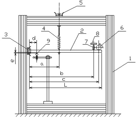
Mass of the electro-exciter is 0.772 kg, electric motor has unbalanced mass 100 g with eccentricity 10 mm, rotation frequency of engine p ranges from 0 to 50 Hz. During experiments frequency of engine was varied from 0 to 5 Hz. Periodic excitation force is:
.
For precise amplitude measurements the contact device – dynamic sensor, based on principle of measuring of the electric field strength between a metallic beam and sensor, is used. Distance is about 15 mm, distance is changeable (in experiments it was 5.0 and 7.5 mm).
Measuring element reading are displayed on the computer monitor.
At the distance of 0.65 m from the axis of rotation the additional mass of 0.3 kg and 0.5 kg are joined to the beam. For comparing the results the additional mass is joined without spring and with conical helical spring.
3. Conical spring properties
The conical spring is not standard equipment. It was custom-built and tested in order to examine vibration dampening. A conical helical spring was fabricated from a high-strength steel wire of 1 mm diameter with the middle diameter of small coil of 13 mm, the middle diameter of large coil of 26 mm, 60 mm high with the permanent angle of slope of coil. Number of coils is 9. Testing of spring was executed to study its behavior under loading, test results are presented in Table 1. Analytical expression for conical spring stiffness characteristic, derived based on the test results is:
Table 1Experimental results of conical helical spring stretching and compression
Spring stretching | ||||||||||
Force , N | 5.0 | 6.0 | 9.0 | 10.0 | 11.00 | 14. | 15.0 | 16.0 | 19.0 | 20.0 |
Deformation x, mm | 14.0 | 17.0 | 26.0 | 28.5 | 31.0 | 39.0 | 42.0 | 45.0 | 54.0 | 57.0 |
Spring compression | ||||||||||
Force , N | 5.0 | 6.0 | 9.0 | 10.0 | 11.0 | 14.0 | 15.0 | 16.0 | 19.0 | 20.0 |
Deformation x, mm | 14.0 | 16.0 | 24.0 | 25.0 | 27.0 | 33.0 | 35.0 | 37.0 | 40.0 | 41.0 |
Plots of spring force dependence on its deflection, based on experimental data and in accordance with analytical expression (1), are shown in Fig. 2.
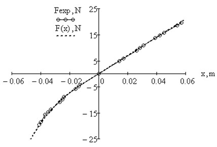


Fig. 2Plots of spring force dependence on its deflection: experimental data, analytical dependence

The dependence between spring force and deflection is linear in the tension zone and partially in compression zone and nonlinear in compression zone.
4. Analytical model of beam. Equations of motion
Fig. 3 provides the scheme of beam and analytical model with the imposed forces. Parameters of vibration system are given in Table 2, were – the moment of inertia of system in relation to the axis of bearing, – natural circular frequency of the system and – natural frequency: , .
Inertia moment for rigid beam, beam with exciter and beam with exciter and additional mass, respectively: , , .
Fig. 3a) Scheme of the beam vibration, b) analytical model of rigid beam
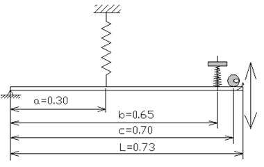
a)
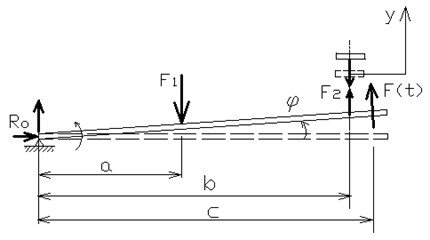
b)
Table 2Parameters of vibration system
System description | , m4 | , s-1 | , Hz |
Beam without exciter | 0.298 | 30.079 | 4.787 |
Beam with exciter | 0.677 | 19.975 | 3.179 |
Beam with exciter and mass 0.3 kg on 0.65 m | 0.803 | 18.332 | 2.918 |
Beam with exciter and mass 0.5 kg on 0.65 m | 0.888 | 17.438 | 2.775 |
Natural circular frequency of mass on spring in linear zone and natural frequency:
, where 350 N/m;
for 0.3 kg, 5.436 Hz; for 0.5 kg, 4.211 Hz.
Motion of beam with the electro-exciter and added mass, taking into account the forces of viscous resistance:
where: , , .
The solution of Eq. (2) – steady-state vibration under action of harmonic exciting force [5]:
Comparing the experimental and theoretical amplitudes for given frequency it is possible to estimate the value of coefficient of viscous resistance .
Motion of beam with an electro-exciter and added mass with conical spring:
where conical spring stiffness coefficients , , are taken in accordance with Eq. (1).
This system has two degrees of freedom and its position is determined by two coordinates: rotation angle of beam round a point and vertical displacement of mass ; - axis is assumed directed upward considering that mass moves vertically. Other forces imposed on the additional mass and beam may be neglected because of small rotation angle.
5. Numerical solutions and experimental results
System (4) and, for comparison, Eq. (2) were solved numerically using Euler’s method with the help of МathCad program for every recorded frequency of excitation force. The examples of the plots of rotation angle dependence on time are given below in Fig. 4 for the beam with additional mass 0.30 kg on conical spring: a) for subresonance value of excitation force frequency, b) for resonance value.
Fig. 4Plots of dependence of beam rotation angle (degrees) on time: μ= 0.5, m= 0.3 kg

a) 2.612 Hz

b) 2.870 Hz
On the basis of received data amplitude-frequency response curve were determined for experimental data and for theoretical calculations. Figs. 5-6 provide amplitude-frequency characteristic for beam with additional mass without spring and with conical spring. Here the maximal amplitude are measured and put on the plot. The amplitude of steady-state vibrations was also measured.
Fig. 5Amplitude-frequency responses for the beam with additional mass m= 0.30 kg: theoretical with μ= 0.5; experimental
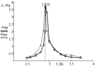
a) Mass without spring
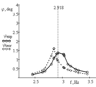
b) Mass with conical spring
Fig. 6Amplitude-frequency responses for the beam with additional mass m= 0.50 kg: theoretical with μ= 0.5; experimental
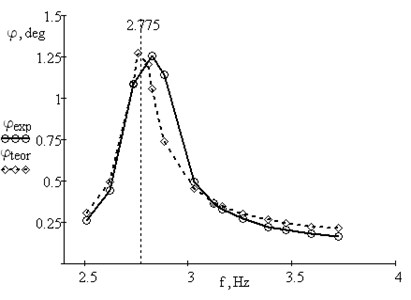
a) Mass without spring
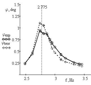
b) Mass with conical spring
As calculations indicate, the spring behaves mainly in a linear fashion. Non-linearity manifests at a large compression in the vicinity of resonance. Viscous resistance is not constant and varies with frequency.
6. Conclusions
This paper reported on the experimental study of dynamic vibration absorber for suppression of rigid beam transversal vibrations. Inertial dynamic vibrations absorber was realized as a mass added to the vibrating object by means of a conical coil spring. Such device reduces oscillations in the vicinity of resonance. A conical coil spring is used because of its ability to resist to the shear forces. Cylindrical coil spring was also tested, which gave a small suppression effect because of arising of bending and lateral vibrations of mass on spring. The mathematical model of inertia dynamic vibration absorber with a nonlinear conical spring was provided. Results of theoretical calculations are in good agreement with experimental findings, thereby confirming the validity of the applied mathematical model.
In future it is necessary to refine the mathematical model by taking into account more carefully joint friction losses and viscous resistance in springs.
References
-
Desai H. D., Nikunj Patel Analytical and experimental investigation of a tuned undamped dynamic vibration absorber in torsion. Proceedings of the World Congress on Engineering, Vol. II, WCE, London, U. K., June 30-July 2, 2010, p. 1555-1560, http://www.iaeng.org/publication/WCE2010/WCE2010_pp1555-1560.pdf
-
De Silva C. W. Vibration. Fundamental and Practice. New York, CRC Press, LLC, 2006.
-
De Silva C. W. Vibration and Shock Handbook. Taylor & Francis Group, LLC, 2005.
-
Harris C. M., Piersol A. G. Harris’ Shock and Vibration Handbook. 5th Ed., New York, McGraw-Hill, 2002.
-
Jablonsky A. A., Noreiko S. S. Theory of Vibration Course. St.-Petersburg, BHV-Peterburg, 2007.
-
Kim S.-M., Wang S., Brennan M. J. Dynamic analysis and optimal design of a passive and an active piezo-electrical dynamic vibration absorber. Journal of Sound and Vibration, Vol. 330, Issue 44, 2011, p. 603-614.
-
Korenev B. G., Reznikov L. M. Dynamic Vibration Absorbers: Theory and Technical Applications. New York, Wiley & Sons, Inc., 1993.
-
Liu K., Liu J. The damped dynamic vibration absorbers: revisited and new result. Journal of Sound and Vibration, Vol. 284, 2005, p. 1181-1189.
-
www.elsevier.com/locate/jsvi, DOI: 10.1016/j.jsv.2004.08.002.
-
Sinha A. Vibration of Mechanical Systems. Cambrige, Cambrige University Press, 2010.
-
Frolov K. V. Vibration in Engineering Technique. Reference Book, Vol. 6, Protection against Vibrations and Impacts, Moscow, Mashinostroenie, 1995.
-
Viet L. D., Park Y. Vibration control of the axisymmetric spherical pendulum by dynamic vibration absorber moving in radial direction. Journal of Mechanical Science and Technology, Vol. 25(7), 2011, p. 1703-1709, www.springerlink.com/content/1738-494x, DOI: 10.1007/s12206-011-0418-8.
-
Yuvaraja M., Senthil Kumar M. Experimental studies on SMA spring based dynamic vibration absorber for active vibration control. European Journal of Scientific Research, Vol. 77, No. 2, 2012, p. 240-251.
About this article
This work has been supported by the ERDF’s grant, within the project “SATTEH”, No. 2010/0189/2DP/2.1.1.2.0/10/APIA/VIAA/019, being implemented in Engineering Research Institute “Ventspils International Radio Astronomy Centre” of Ventspils University College (VIRAC).
